
Method and device with dynamic dormancy

a technology of dynamic dormancy and device, which is applied in the field of method and device with dynamic dormancy feature, can solve the problems of user being surprised and/or frustrated when the battery runs, not being convenient or even possible for a user to recharge, and being easily damaged or damaged,

Inactive Publication Date: 2011-12-29
GOOGLE TECH HLDG LLC
View PDF3 Cites 100 Cited by
  • Summary
  • Abstract
  • Description
  • Claims
  • Application Information

AI Technical Summary

Problems solved by technology

While the power storage device is generally rechargeable, it may not be convenient or even possible for a user to recharge.
Additionally, different operating environments can cause the user to be surprised and / or frustrated when the battery runs out much more quickly than would typically be expected by the user.
Thus, a variation from the norm or unexpected short battery life is very undesirable from a user perspective.
This is a particularly relevant problem for mobile computing devices running applications supported by an applications server because of the power drain due to the wireless data exchange between the mobile device and the server, since each upload or download causes the consumption of energy in the mobile device and server.
The problem is especially acute in the mobile device, which is typically battery powered and has finite energy available.
A worst case RTT value may occur under adverse signaling conditions such as low signal power, low receiver level, high interference or poor received data quality.
For example, for a web-browsing application it may be determined that there is a high probability of a delayed mobile device user response.

Method used


Image

  • Method and device with dynamic dormancy
  • Method and device with dynamic dormancy
  • Method and device with dynamic dormancy

Examples


Embodiment Construction

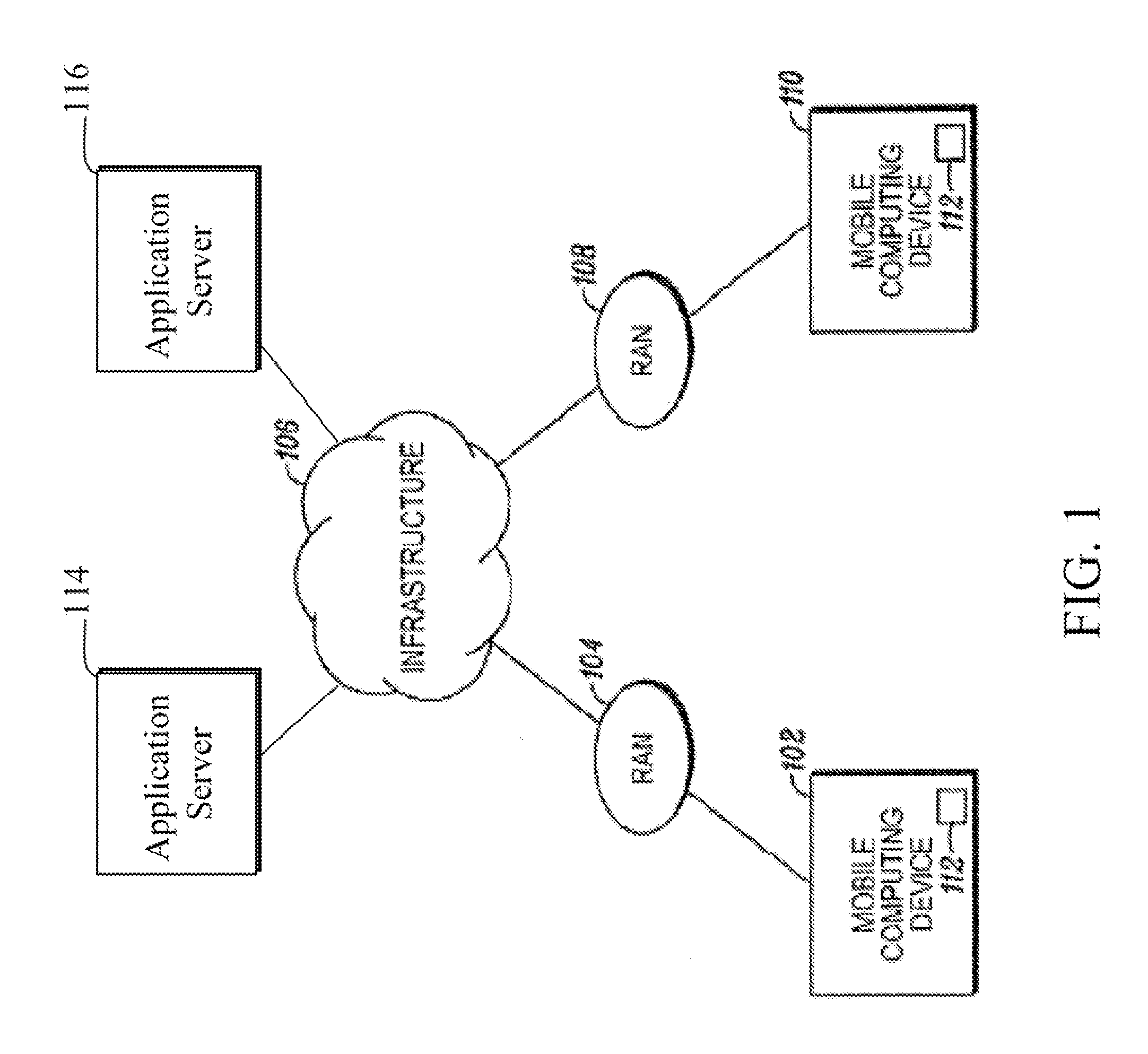
[0023]Referring to FIG. 1, one example of a system with efficient server communication for increasing the battery life of a mobile computing device, is described. The system includes a first mobile computing device 102 that is coupled to a first Radio Access Network (RAN) 104. The first RAN 104 is coupled to a communication infrastructure 106. The infrastructure can include a plurality of application servers, for running various applications, as detailed below. A second mobile computing device 110 is coupled to a second RAN 108. The second RAN 108 is also coupled to the infrastructure 106. The system includes application servers 114 and 116 for running applications in synchronous communications with mobile devices 102, 110. The principles described herein may be applied to a variety of wide area network systems, such as 2G and 3G networks, long-term evolution (LTE), ultra mobile wideband (UMB), 802.16e & m, High Rate Packet Data (HRPD) systems, or systems such as the Universal Mobil...


PUM


Abstract

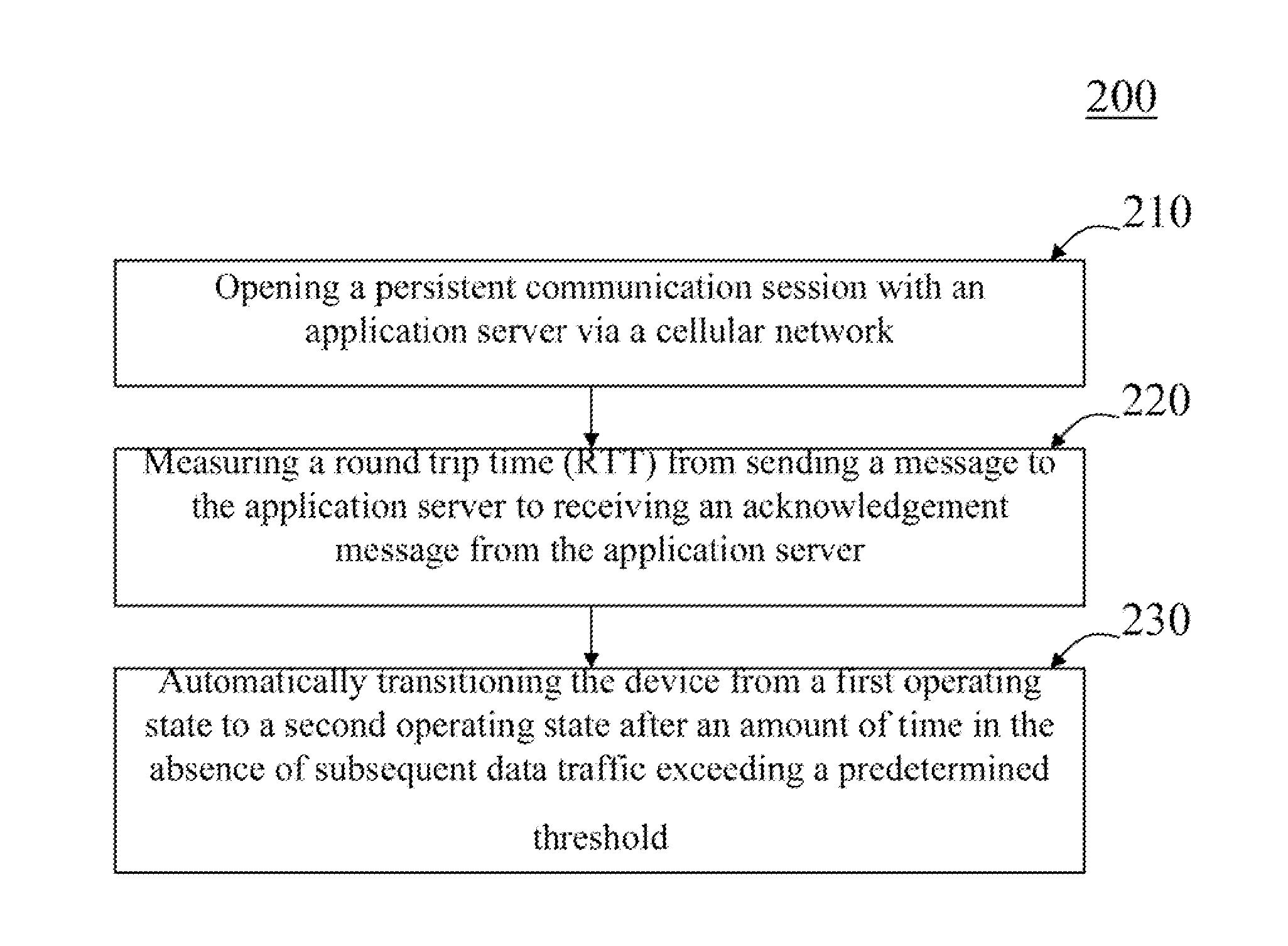
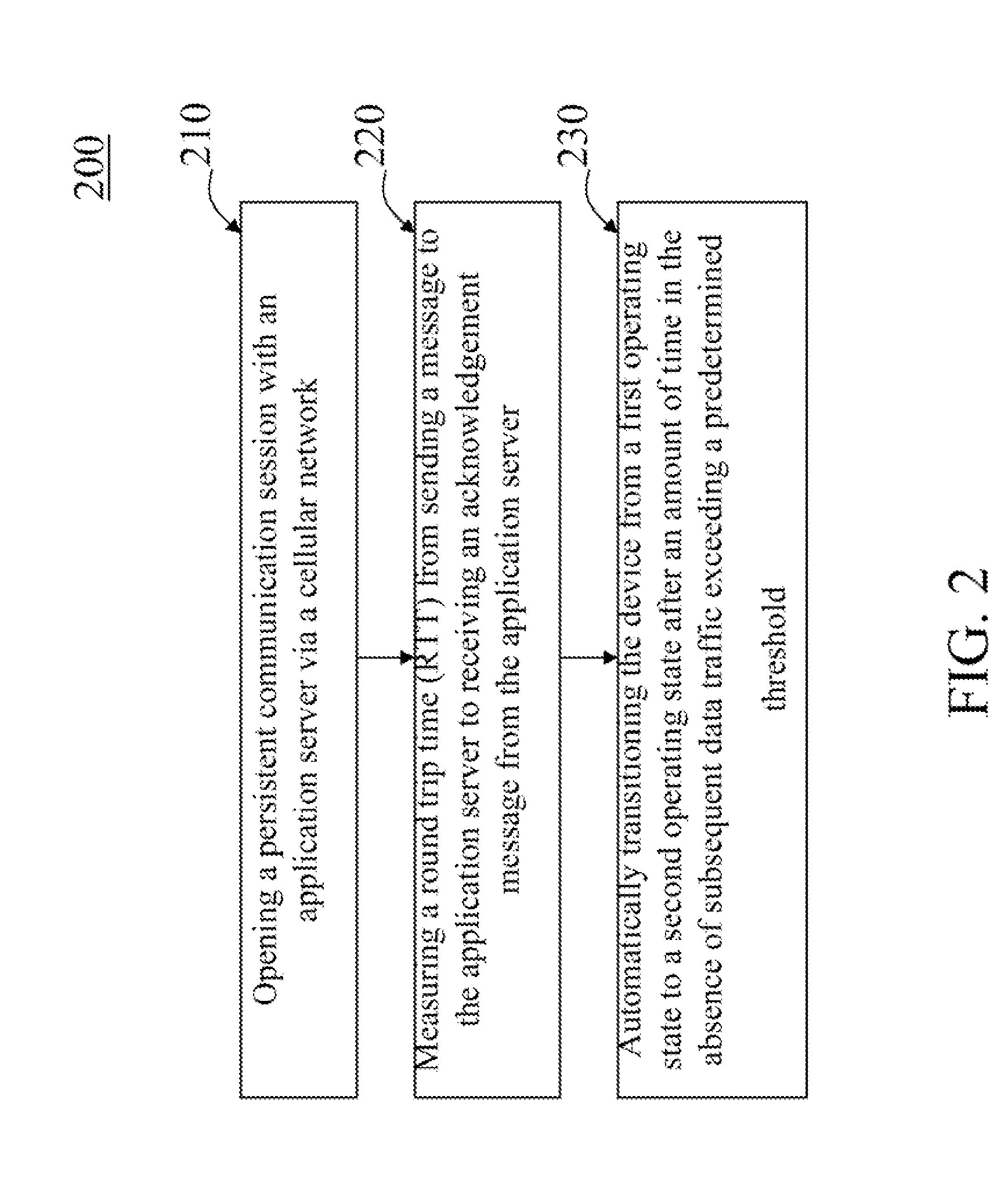
A method (200) and device (300) for saving energy in a wireless communication device configured to maintain a persistent communication session over a wireless network with an application server. The method (200) can include: opening (210) a persistent communication session with an application server via a cellular network; measuring (220) a round trip time (RTT) from sending a message to the application server to receiving an acknowledgement message from the application server; and automatically transitioning (230) the device from a first operating state to a second operating state after an amount of time in the absence of subsequent data traffic exceeding a predetermined threshold, wherein power consumption associated with the second operating state is less than power consumption associated with the first operating state, and the predetermined threshold is a function of the measured round trip time. Advantageously, the method (200) can measure the actual RTT and transition to a low power based on the measured RTT exceeding a predetermined threshold, before the expiration of a network configured inactivity timer and in the absence of subsequent data traffic, which helps to minimize unnecessary power drain in a wireless communication device and minimizes inefficiencies in connection with data exchanges between a network and a wireless communication device.

Description

FIELD OF THE INVENTION[0001]The field of the invention relates to a method and device with a dynamic dormancy feature that can help to reduce energy drain.BACKGROUND OF THE INVENTION[0002]Mobile computing devices, such as mobile or wireless stations, cell phones, radios, laptops, wireless communication devices and the like, operate with a power storage device with a limited energy supply, such as a battery, fuel cell or the like. A mobile computing device needs a power source and, in many cases, this power source is a battery. For instance, cellular phones use various types of batteries to operate. The amount of time a mobile station can typically operate before the energy of the battery is consumed (which is often referred to as “battery life”), is often an important criteria that consumers use in choosing one brand or type of mobile computing device over another brand. The terms battery, energy storage device and power storage device are used interchangeably herein.[0003]While the...

Claims


Application Information

Patent Timeline
Patent Type & Authority Applications(United States)
IPC IPC(8): H04W52/02
CPCH04W52/0225Y02B60/50H04W52/028Y02D30/70H04W52/02
Inventor LENART, ANDREW W.BLACK, GREGORY R.KLEMENTIEV, OLEG Y.MARCHEVSKY, VALERIY F.
Owner GOOGLE TECH HLDG LLC
Learn More