Continuously variable transmission mechanism and transmission using the same

a transmission mechanism and variable technology, applied in the direction of friction gearings, belts/chains/gearings, friction gearings, etc., can solve the problems of complicated control, mechanism expansion, complicated control, etc., and achieve the effect of reducing the rotational speed of one, increasing and reducing the rotational speed of the other rotary member

Inactive Publication Date: 2011-12-29
TOYOTA JIDOSHA KK
View PDF3 Cites 142 Cited by
  • Summary
  • Abstract
  • Description
  • Claims
  • Application Information

AI Technical Summary

Benefits of technology

[0012]The second rotary member and the third rotary member are contacted with the outer face of the rolling member in a torque transmittable manner on both sides of the rolling member across a line passing through a center of the rolling member and a contact point at which the rolling member is contacted with the first rotary member. According to the continuously variable transmission mechanism, a rotational speed of one of the second and the third rotary members is lowered by inclining the rotational center axis of the rolling member in a manner to increase a rotational speed of the other rotary member.
[0018]According to the present invention, the second rotary member and the third rotary member are contacted with the outer face of the rolling member on both sides of the rolling member across the maximum rotation radius of the rolling member. Therefore, the rotation radius of the contact point between the rolling member and any one of the rotary member is increased and the rotational radius of the contact point between the rolling member and the other rotary member is decreased by inclining the rolling member to change the tilt angle of the rotational center axis of the rolling member. That is, a speed change in a direction to increase a speed and a speed change operation in a direction to reduce a speed can be carried out simultaneously.
[0020]In addition to the above-explained advantage, the transmission of the present invention is capable of reducing the rotational speed of one of the rotary members simultaneously with increasing the rotational speed of the other rotary member by tilting the rolling member. Therefore, in case the power is being transmitted from one of the rotary members to the output member through a predetermined transmission mechanism, the rotational speed of the other transmission mechanism which is not transmitting the torque to the output member and the rotational speed of the output shaft or the intermediate shaft are synchronized gradually with each other by tilting the rolling member. In this synchronous situation, the engagement member being disengaged is engaged, and the engagement member being engaged is disengaged. For this reason, the transmission mechanism to be involved in a transmission of the torque to the output member can be shifted smoothly without changing the rotational speeds abruptly so that a resultant abrupt change in an inertia torque can be avoided.
[0021]In addition to above-explained advantages, according to the present invention, dog clutches are used as the switching mechanisms. Therefore, no slippage will occur even during transmitting the torque through the switching mechanism. For this reason, a power loss can be reduced. Especially, in case of using the dog clutch in the transmission as claimed in claim 5, the rotational speed will not be changed abruptly so that an occurrence of shocks resulting from an abrupt change in the rotational speed can be avoided.

Problems solved by technology

In this case, the mechanism is enlarged and a complicated control is required to control the mechanism thus enlarged.
That is, the mechanism is also enlarged in this case, and a complicated control is required to control the mechanism thus enlarged.

Method used


Image

  • Continuously variable transmission mechanism and transmission using the same
  • Continuously variable transmission mechanism and transmission using the same
  • Continuously variable transmission mechanism and transmission using the same

Examples


Embodiment Construction

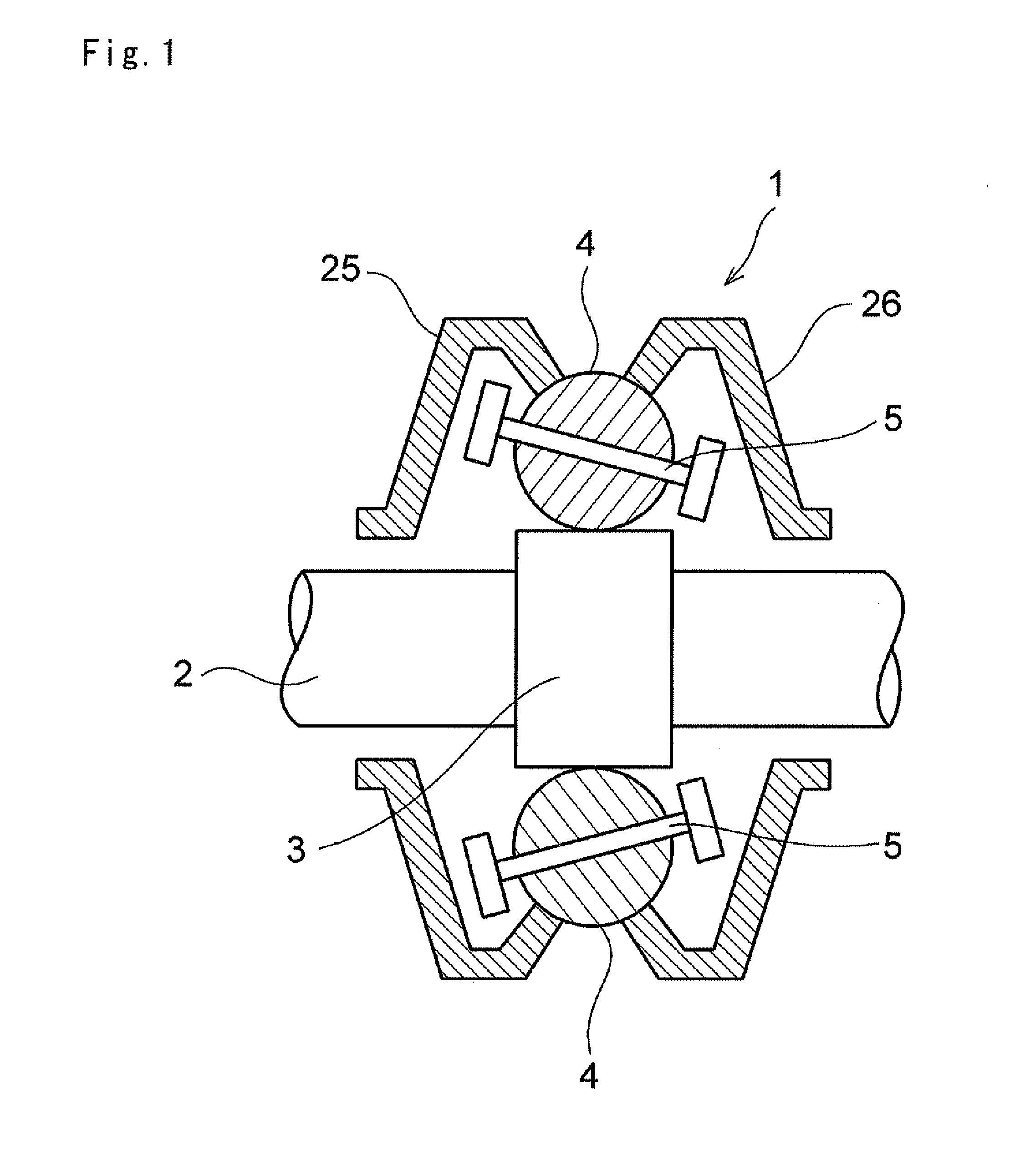
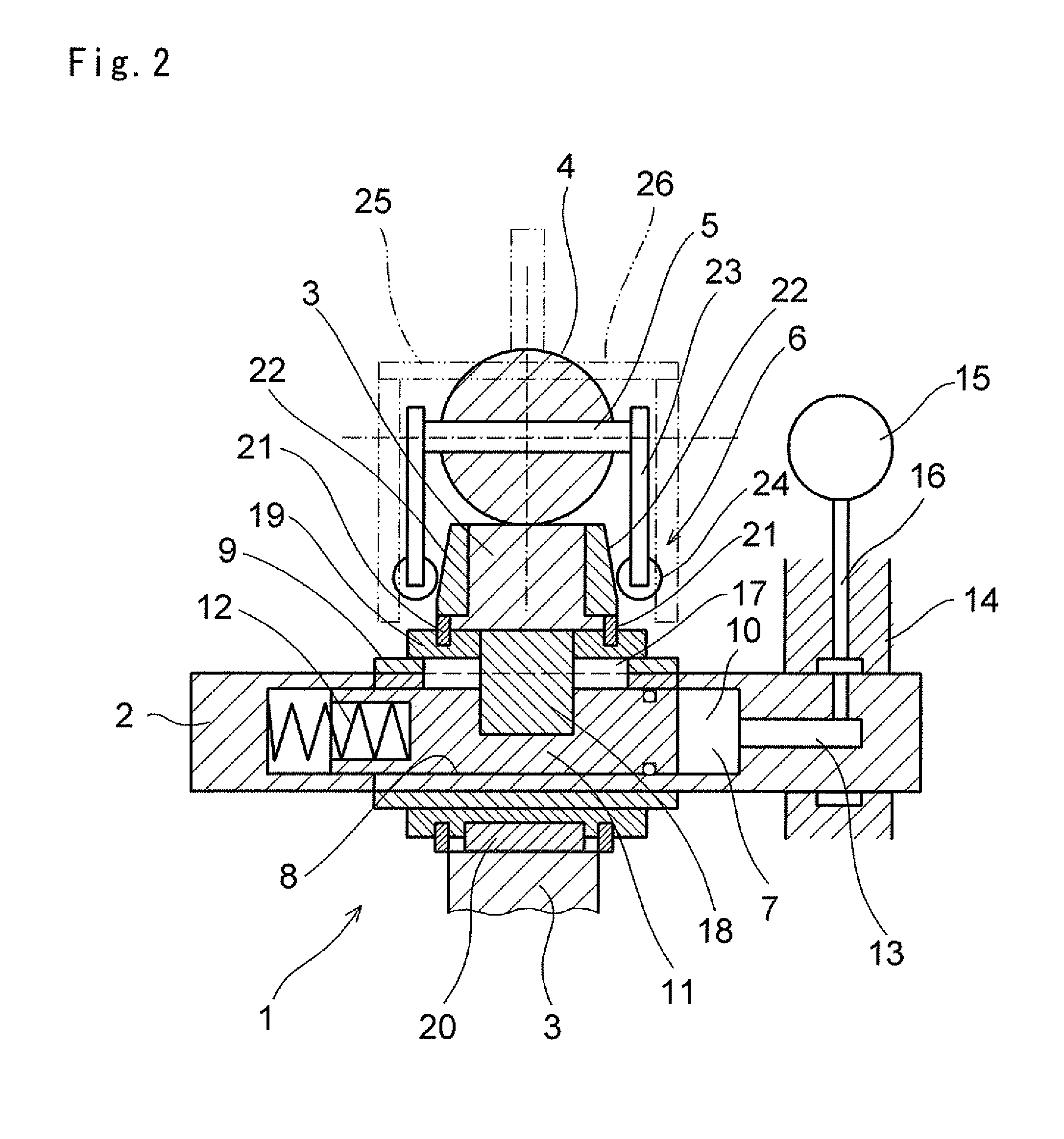
[0030]Next, this invention will be described in connection with its specific examples. As shown in FIG. 1, a continuously variable transmission mechanism 1 is configured to transmit a torque among three rotary elements, and to continuously vary a speed change ratio between a first rotary element and a second rotary element and a speed change ratio between the first rotary element and a third rotary element. In FIG. 1, reference numeral 2 represents an input shaft, and a roller 3 is fitted onto the input shaft 2 to be rotated integrally with the input shaft 2. Specifically, the roller 3 is a cylindrical member, and an outer circumferential face thereof serves as a torque transmission face. In addition, a plurality of rolling members 4 are arranged around the torque transmission face while being contacted therewith.

[0031]As explained later, the rolling member 4 is adapted to mediate a torque transmission, and to vary a speed change ratio. For this purpose, an outer circumferential fac...


PUM


Abstract

A continuously variable transmission adapted to set a speed change ratio in accordance with a tilt angle of a rolling member mediating a torque being transmitted, and to transmit a torque among three elements. The transmission mechanism is provided with a rolling member having a smooth outer face and capable of tilting a rotational center axis thereof, and a rotary member arranged to be contacted with a predetermined portion of the outer face of the rolling member in a torque transmittable manner. Specifically, the continuously variable transmission mechanism is configured to vary a rotational speed of the rotary member by changing a rotation radius of a contact point between the rolling member and the rotary member by tilting the rotational center axis of the rolling member.

Description

TECHNICAL FIELD[0001]This invention relates to a continuously variable transmission mechanism adapted to vary a speed change ratio as a ratio between an input speed and an output speed, and a transmission using said continuously variable transmission mechanism.BACKGROUND ART[0002]In a known mechanism for varying a speed change ratio continuously, a rolling member such as a disc and a roller is interposed between a member of driving side and a member of driven side. According to the known mechanism of this kind, the speed change ratio is varied continuously by changing a connecting state between the member of driving side or driven side. For example, a toroidal type continuously variable transmission is known as the mechanism of this kind. Another example is disclosed in Japanese Patent Laid-Opens No. 6-257655 and No. 2008-75878. The continuously variable transmission disclosed therein is provided with a ball capable of tilting a rotation axis thereof, and members of driving and driv...

Claims


Application Information

Patent Timeline
Patent Type & Authority Applications(United States)
IPC IPC(8): F16H37/06F16H15/04
CPCF16H37/021F16H15/28
Inventor OGAWA, HIROYUKITOMOMATSU, DAISUKEMURAKAMI, AKIRA
Owner TOYOTA JIDOSHA KK
Why Eureka
Try Eureka