[0006]Therefore, it is a primary objective of the present invention to provide a hydraulic pressure control device that suppresses rapid engagement of a clutch when a differential pressure between an engagement side oil chamber defined on one side of a piston included in the clutch and a back-pressure side oil chamber defined on the other side of the piston is relatively small.
[0009]This hydraulic pressure control device according to the first aspect is capable of controlling the differential pressure between the engagement side oil chamber and the back-pressure side oil chamber by supplying the engagement pressure generated by the engagement pressure generating valve to the engagement side oil chamber defined on the one side of the piston included in the clutch via the first oil passage, and also supplying the
clutch control pressure generated by the
clutch control pressure generating valve to the back-pressure side oil chamber defined on the other side of the piston via the second oil passage. Here, when the differential pressure between the engagement side oil chamber and the back-pressure side oil chamber is made small in order to place the clutch in the slip state or make it stand by in the state immediately before engagement, the hydraulic pressure in the engagement side oil chamber can be higher than the engagement pressure generated by the engagement pressure generating valve for some reason. In such a case, the hydraulic pressure in the back-pressure side oil chamber is increased by a force acting on the hydraulic oil in the back-pressure side oil chamber from the engagement-side oil chamber side via the piston, and the hydraulic pressure supplied as a feedback pressure from the back-pressure-side oil chamber side to the clutch control pressure generating valve is increased. Accordingly, the clutch control pressure generating valve operates so as to reduce the clutch control pressure, whereby the hydraulic pressure in the back-pressure side oil chamber is reduced with the hydraulic pressure in the engagement side oil chamber increased. As a result, the clutch may be engaged rapidly. In consideration of this problem, in the hydraulic pressure control device described above, the first oil passage connected to the engagement side oil chamber and the second oil passage connected to back-pressure side oil chamber are communicated with each other via the bypass oil passage having the orifice in a midway position thereof. With this structure, even if the hydraulic pressure supplied as a feedback pressure from the back-pressure-side oil chamber side to the clutch control pressure generating valve is increased by an increase in the hydraulic pressure in the engagement side oil chamber, and accordingly, even if the clutch control pressure generated by the clutch control pressure generating valve is reduced, the hydraulic oil from the engagement pressure generating valve can be allowed to flow from the first oil passage to the second oil passage so as to suppress reduction in the hydraulic pressure in the back-pressure side oil chamber. In addition, by providing the orifice in the bypass oil passage, the flow rate of the hydraulic oil from the first oil passage into the second oil passage can be set more appropriately. Therefore, with this hydraulic pressure control device, it is possible to satisfactorily suppress rapid engagement of the clutch when the differential pressure between the engagement side oil chamber and the back-pressure side oil chamber is small.
[0010]According to a second aspect of the present invention, the engagement side oil chamber may be a hydraulic
power transmission chamber in which power is transmitted, via hydraulic oil, between an input-side hydraulic
power transmission element and an output-side hydraulic
power transmission element that are included in a hydraulic transmission apparatus. That is, according to the second aspect, even if the hydraulic pressure supplied as a feedback pressure from the back-pressure-side oil chamber side to the clutch control pressure generating valve is increased by an increase in the hydraulic pressure in the engagement side oil chamber (hydraulic power transmission chamber) due to the centrifugal hydraulic pressure occurring with rotation of the input-side hydraulic power transmission element and the output-side hydraulic power transmission element, and accordingly, even if the clutch control pressure generated by the clutch control pressure generating valve is reduced, the hydraulic oil from the engagement pressure generating valve can be allowed to flow from the first oil passage into the second oil passage so as to suppress reduction in the hydraulic pressure in the back-pressure side oil chamber, whereby rapid engagement of the clutch can be satisfactorily suppressed.
[0011]According to a third aspect of the present invention, the engagement pressure generating valve may be a modulator valve that is capable of regulating a line pressure to generate a constant modulator pressure. According to the third aspect, the fluctuation of the hydraulic pressure in the engagement side oil chamber can be suppressed, and the hydraulic pressure in the back-pressure side oil chamber can be maintained in a more
stable state when the hydraulic pressure supplied as a feedback pressure from the back-pressure-side oil chamber side to the clutch control pressure generating valve is increased by an increase in the hydraulic pressure in the engagement side oil chamber, and accordingly, when the clutch control pressure is reduced.
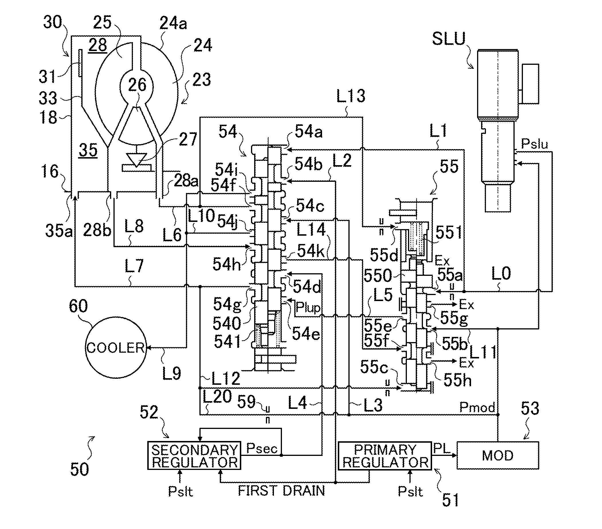
[0012]According to a fourth aspect of the present invention, the clutch may be a lock-up clutch, and the hydraulic pressure control device may further include a linear
solenoid valve that generates a lock-up control pressure, and a lock-up
relay valve that establishes, when the lock-up control pressure is supplied from the linear
solenoid valve, a lock-up ON state that permits the supply of the engagement pressure from the engagement pressure generating valve to the engagement side oil chamber via the first oil passage and the supply of the clutch control pressure from the clutch control pressure generating valve to the back-pressure side oil chamber via the second oil passage, and establishes, when the lock-up control pressure is not supplied from the linear
solenoid valve, a lock-up OFF state that restricts the supply of the engagement pressure from the engagement pressure generating valve to the engagement side oil chamber via the first oil passage and allows a circulating pressure generated by a circulating pressure generating valve to be supplied to the back-pressure side oil chamber. According to the fourth aspect, by causing the linear solenoid valve to generate the lock-up control pressure, the lock-up
relay valve can be switched from the lock-up OFF state to the lock-up ON state, and the differential pressure between the engagement side oil chamber and the back-pressure side oil chamber can be controlled.

