Valve control apparatus

a valve control and valve technology, applied in the direction of valve operating means/releasing devices, machine/engine, service pipe systems, etc., can solve the problems of disadvantageous increase in sensing error

Inactive Publication Date: 2012-01-05
DENSO CORP
View PDF13 Cites 36 Cited by
  • Summary
  • Abstract
  • Description
  • Claims
  • Application Information

AI Technical Summary

Benefits of technology

[0027]The present invention addresses the above disadvantages. According to the present invention, there is provided a valve control apparatus, which includes a valve, an actuator having a rod, a link mechanism, and means (hereinafter, referred to as sensing means) for sensing an amount of displacement of the rod in the axial direction of the rod. The valve is adapted to open or close a flow passage. The actuator includes a rod and a rod bearing and drives the rod to reciprocate the rod and to drive the valve through the rod. The rod bearing slidably supports the rod to enable slide motion of the rod in an axial direction while enabling swing motion of the rod about a bearing center of the rod bearing. The link mechanism includes a lever, which connects between the valve and the rod and converts linear motion of the rod into rotational motion of the valve. The actuator is driven to control opening and closing of the valve based on the amount of displacement of the rod in the axial direction of the rod, which is sensed by the sensing means. The lever includes a rotational axis, which is coaxial with a rotational axis of the valve, at a valve-side connection of the lever that is rotatably connected to the valve. The lever includes a rod-side connection that is rotatably connected to the rod. A rotational moving point of the rod-side connection is adapted to swing between a full close point and a full open point along a rotational moving path, which is a curved path centered at the rotational axis of the valve-side connection of the lever and has a predetermined radius of curvature. When an opening degree of the valve becomes a full close degree to fully close the flow passage, the rotational moving point of the rod-side connection, which is moved along the rotational moving path, is placed in the full close point along the rotational moving path. When the opening degree of the valve becomes a full open degree to fully open the flow passage, the rotational moving point of the rod-side connection, which moves along the rotational moving path, is placed in the full open point along the rotational moving path. When the opening degree of the valve becomes a half degree, which is one half of an angular degree between the full close degree and the full open degree, the rotational moving point of the rod-side connection is placed in a half point between the full close point and the full open point along the rotational moving path. An apex of swing of the rotational moving point of the rod-side connection, which is adapted to swing between the full close point and the full open point along the rotational moving path, is set at a point, which is located between the full close point and the half point along the rotational moving path and satisfies a relationship of OP>OA. Here, OP denotes an angle that is defined between a first imaginary line (straight line), which connects between the bearing center and the full open point, and a second imaginary line (straight line), which connects between the bearing center and the apex of the swing, and OA denotes an angle that is defined between the first imaginary line and a third imaginary line (straight line), which connects between the bearing center and the full close point.

Problems solved by technology

Therefore, in the case where the amount of the stroke of the rod 105 is directly sensed with the magnetic sensor, a sensing error may be disadvantageously increased due to the swing motion of the rod 105.
Therefore, in the case where the amount of the stroke of the rod 205 is directly sensed with the magnetic sensor, a sensing error may be disadvantageously increased due to the swing motion of the rod 205.

Method used


Image

  • Valve control apparatus
  • Valve control apparatus
  • Valve control apparatus

Examples


Embodiment Construction

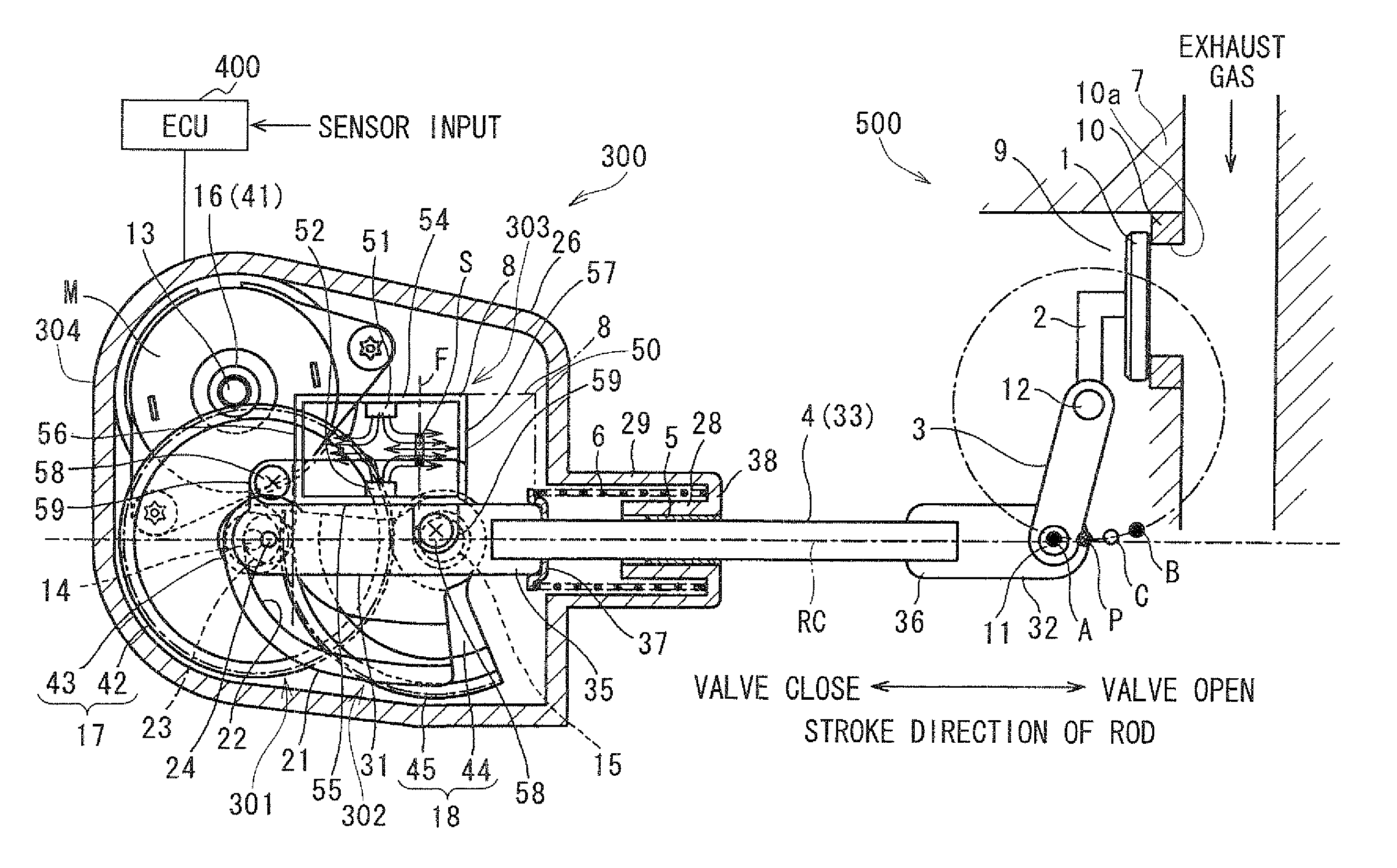
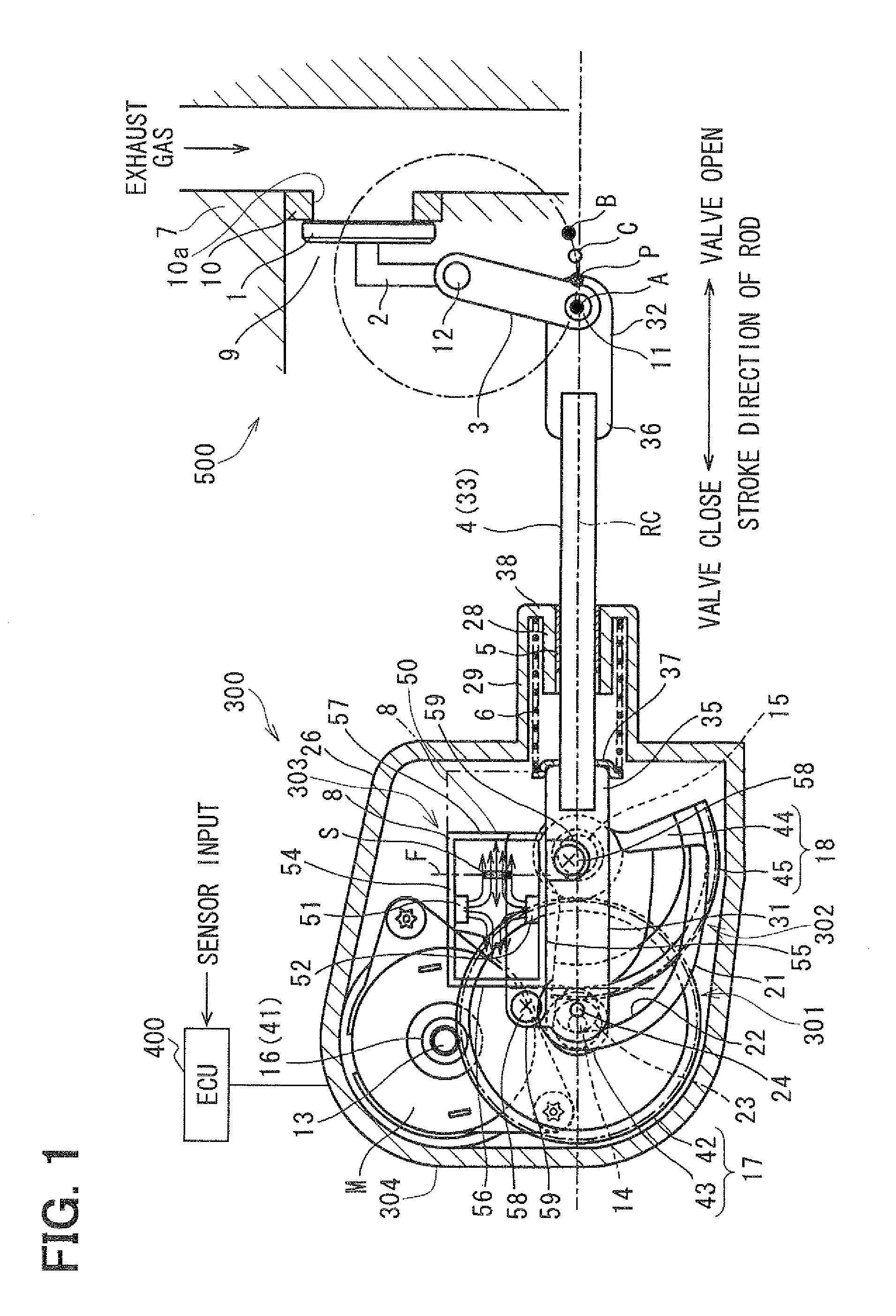
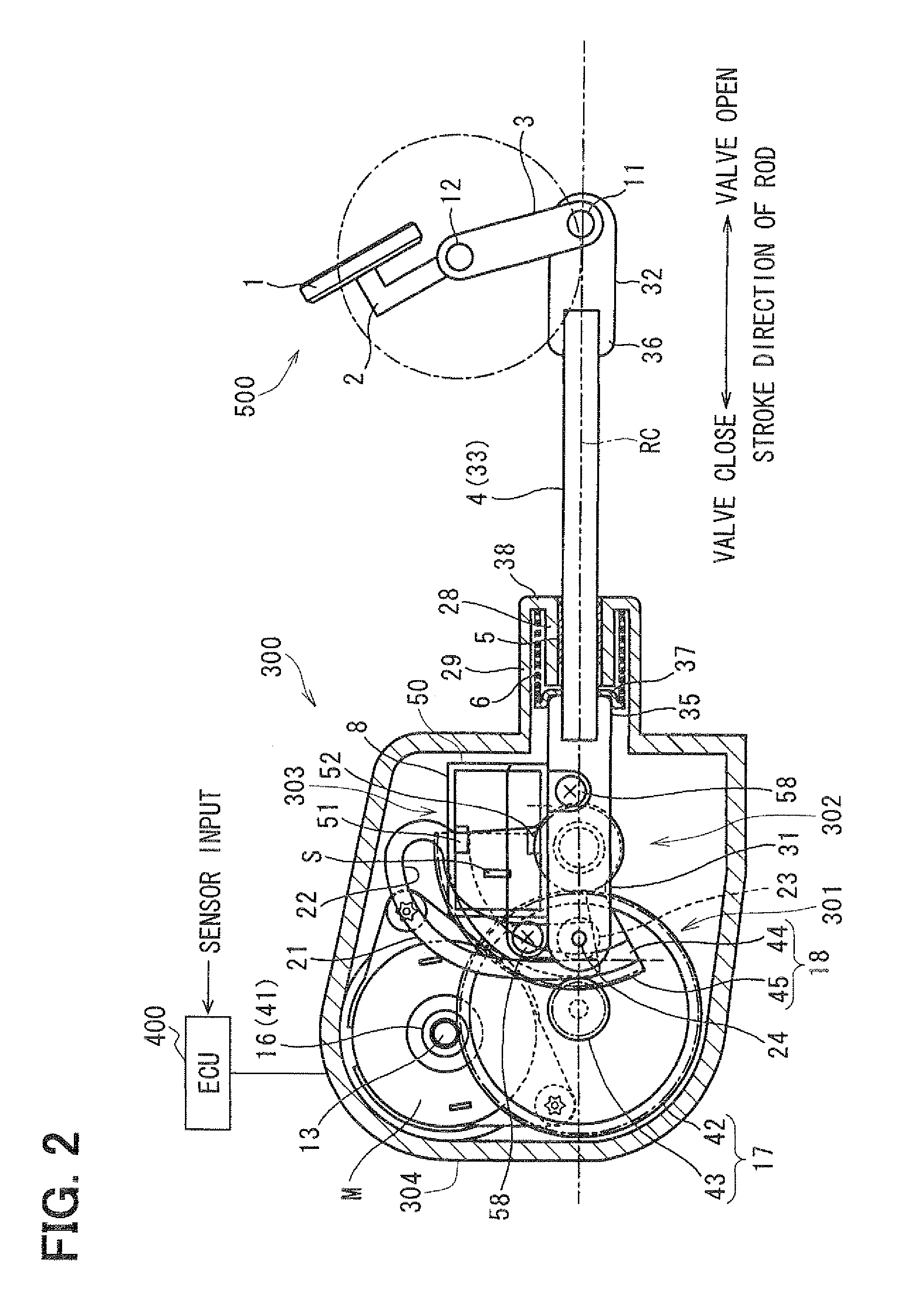
[0045]Now, an embodiment of the present invention will be described. FIGS. 1 to 78 show an embodiment of the present invention. Specifically, FIG. 1 shows a positional relationship between a link lever and a rod at the time of fully closing a wastegate valve. FIG. 2 shows a positional relationship between the link lever and the rod at the time of fully opening the wastegate valve.

[0046]A wastegate valve control apparatus of an internal combustion engine of the present embodiment is implemented in a boost pressure control apparatus of the internal combustion engine. The wastegate valve control apparatus includes a wastegate valve 1, a link mechanism 500, an electric actuator 300 and an engine control unit (ECU) 400. The wastegate valve 1 controls a flow quantity of exhaust gas of the internal combustion engine. The link mechanism 500 includes a link lever 3, which is connected to a shaft 2 of the wastegate valve 1. The electric actuator 300 includes a rod 4, which is connected to the...


PUM


Abstract

A rotational moving point of a connection between a rod and a valve swings between a full open point, at which the valve is fully opened, and a full close point, at which the valve is fully closed. An apex of this swing is set at a point, which is between the full close point and a half point and satisfies a relationship of θP>θA where θP denotes an angle that is defined between a first imaginary line, which connects between a bearing center of a rod bearing and the full open point, and a second imaginary line, which connects between the bearing center and the apex of the swing, and θA denotes an angle that is defined between the first imaginary line and a third imaginary line, which connects between the bearing center and the full close point.

Description

CROSS REFERENCE TO RELATED APPLICATION[0001]This application is based on and incorporates herein by reference Japanese Patent Application No. 2010-148796 filed on Jun. 30, 2010, Japanese Patent Application No. 2010-151833 filed on Jul. 2, 2010 and Japanese Patent Application No. 2010-268265 filed on Dec. 1, 2010.BACKGROUND OF THE INVENTION[0002]1. Field of the Invention[0003]The present invention relates to a valve control apparatus.[0004]2. Description of Related Art[0005]For example, Japanese Unexamined Patent Publication No. H10-103069A teaches a boost pressure control apparatus, which includes a wastegate valve that opens or closes a wastegate passage of a turbocharger.[0006]As shown in FIGS. 8 to 10B, the boost pressure control apparatus of Japanese Unexamined Patent Publication No. H10-103069A includes a rotatable shaft 102, which supports and drives the wastegate valve 101. A link lever 103 is connected to the rotatable shaft 102, and a rod 105 of a diaphragm actuator 104 is ...

Claims


Application Information

Patent Timeline
Patent Type & Authority Applications(United States)
IPC IPC(8): F16K31/44
CPCF02B37/186F16K31/521F16K31/043Y02T10/144F16K37/0041F16K37/0033Y10T137/8242Y02T10/12
Inventor TAKEDA, TETSUMAFUKUMORI, SADAHITOYAMANAKA, TETSUJISHIMADA, HIROKI
Owner DENSO CORP
Why Eureka
Try Eureka