
3D Graphic Insertion For Live Action Stereoscopic Video

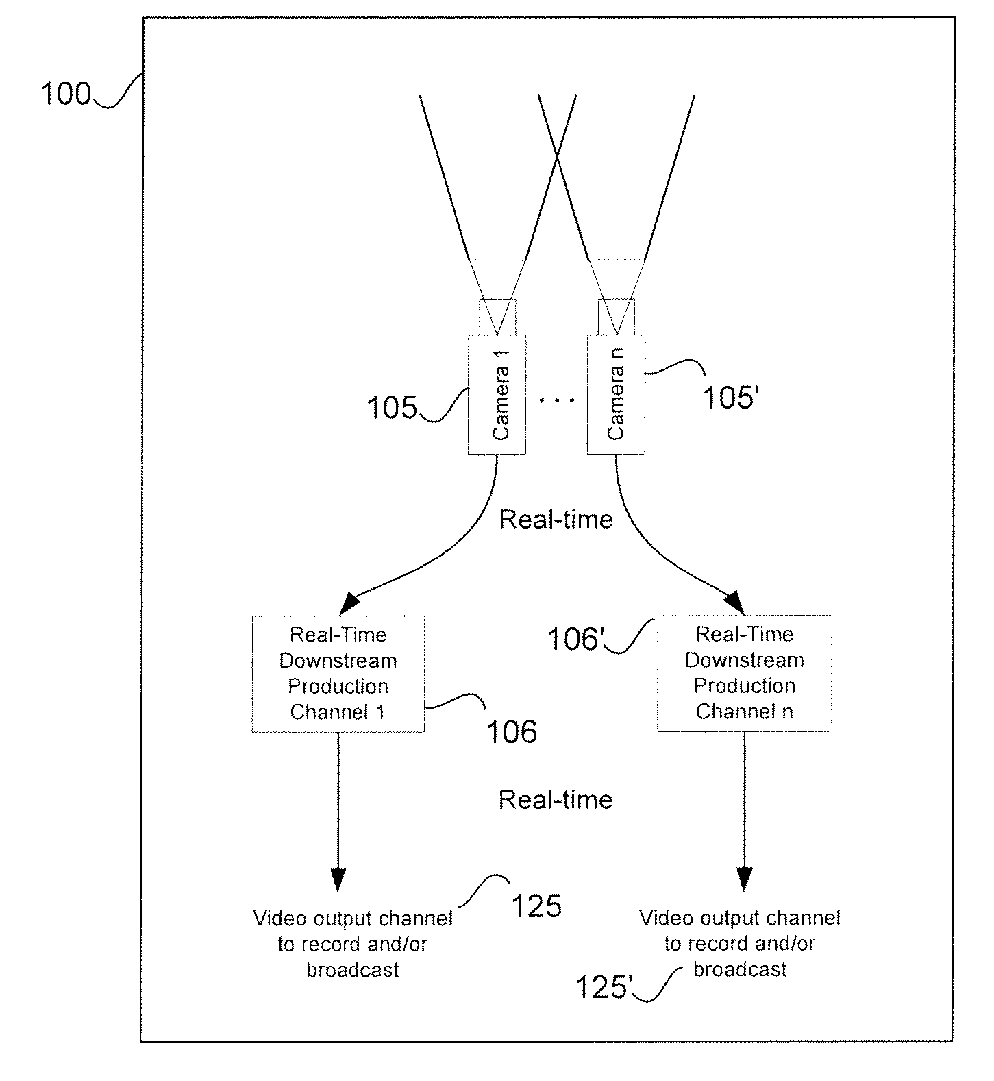
a stereoscopic video and 3d graphic technology, applied in the field of realtime three-dimensional live video production, can solve problems such as breaking the illusion of graphic elements

Active Publication Date: 2012-01-05
DISNEY ENTERPRISES INC
View PDF19 Cites 66 Cited by
  • Summary
  • Abstract
  • Description
  • Claims
  • Application Information

AI Technical Summary

Benefits of technology

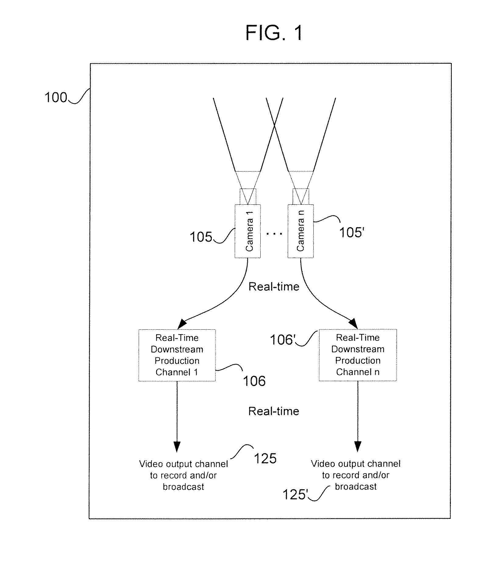
[0008]There is a need for inserting graphics into stereoscopic content for applications such as the first and ten line for football. Technology innovations are required to insert these graphic elements in a manner which maintains the illusion of the graphics being located at defined positions in the 3D space being shot by stereoscopic camera rigs.
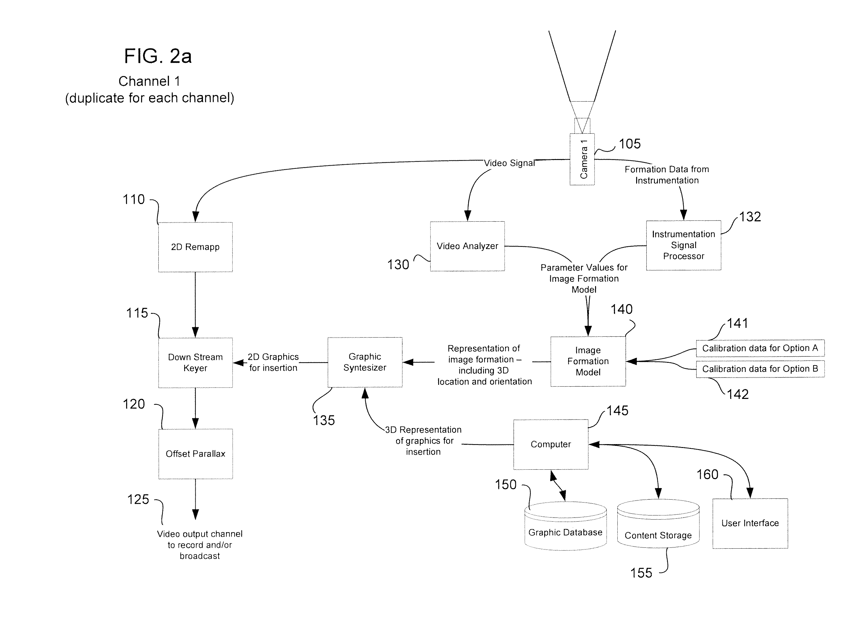
[0011]The insertion of graphics into traditional 2D live action video requires precise correspondence between the graphic elements and the scene being viewed by the camera. This, in turn, requires graphic elements be generated by a virtual camera whose image formation properties match those of the real camera creating the video. A camera model needs to be employed that represents all of relevant image formation characteristics and that this camera model tracks the actual camera's image formation characteristics in real time. Any errors between the virtual camera model and the actual camera can cause disparity between the graphic elements and the actual scene being shot which breaks the illusion of the graphic elements actually being a part of the real scene.
[0012]For an idealized camera, the virtual camera model should match the location, orientation, and optical magnification of the real camera. Furthermore, the virtual camera should also match all the real camera image formation characteristics which include optical distortion (typically radial distortion), image sensor mounting in the camera relative to the optics (typically tangential distortion), and accurately model the kinematics of camera mounting and control and systematic measurement errors in the instrumentation of the camera kinematics and optics. Any errors in modeling and representation of these characteristic can result in shifting or scaling of graphics relative to the actual scene (real situs).
[0019]In another embodiment, the video stream may receive full 2D spatial remapping of the entire video streams prior to the graphic insertion. Under such remap processing the remapped stream can be incorporated into the virtual camera model used for generating the graphical elements. The remapping can additionally be used to compensate for deficiencies in the design of any particular stereoscopic camera rig. For example, the remapping process may be used with respect to a stereoscopic camera rig using toe-in. Such use creates keystoning of the video channels resulting in selective vertical disparity that may be unacceptable for high quality stereoscopic content. The remapping can be used to compensate for the keystoning, creating high quality stereoscopic video content and allowing the graphic insertion to be done to a more ideal set of conditions. Further exemplary uses of the remapping process may be to correct for optical distortion and to correct for sensor misalignment. The effects of optical distortion and sensor misalignment are typically seen as radial and tangential distortion respectively. These effects can be corrected through the use of the remapping process. This can be applied independently to each camera / lens of the stereoscopic pair and uniquely for each such stereoscopic camera head being used.

Problems solved by technology

Any errors between the virtual camera model and the actual camera can cause disparity between the graphic elements and the actual scene being shot which breaks the illusion of the graphic elements actually being a part of the real scene.

Method used


Image

  • 3D Graphic Insertion For Live Action Stereoscopic Video
  • 3D Graphic Insertion For Live Action Stereoscopic Video
  • 3D Graphic Insertion For Live Action Stereoscopic Video

Examples


Embodiment Construction

[0030]Disclosed in embodiments herein is a method and system for a insertion of computer graphic objects into stereoscopic content for use in live 3D video streaming production and broadcast.

[0031]Graphic elements are added to video image streams to enhance a video production and add to the overall viewing experience of a viewer. Graphics can include, among others, first down line markers, object trackers, dynamic marking tools and telemetry interfaces. Object trackers, shown as icons on the screen, can include parameterized models that viewers see tracking players, race cars, footballs, hockey pucks, golf balls and the like. The tracker icon may be modeled so as to remain keyed in one place on the screen or alternatively to move with the object being tracked or move so as to avoid covering predetermined objects, such as a player's body or particularly the head of a player or participant. Similarly, a tracker icon for a race car might be modeled to follow a vehicle wherein the icon ...


PUM


Abstract

Systems and methods for the insertion of graphics into stereoscopic live action 3D video using image models taking into account positional data from the stereoscopic camera rig.

Description

BACKGROUND OF THE INVENTION[0001]1. Field of the Invention[0002]The present invention relates generally to the production of real-time three dimensional live video.[0003]2. Description of the Related Art[0004]All references cited in this specification, and their references, are incorporated by reference herein where appropriate for teachings of additional or alternative details, features, and / or technical background.[0005]Sporting event broadcasting has increasingly made use of graphic objects overlaid on two-dimensional (2D) video production streams, such as with NASCAR car tracking and with American football first and ten lines. The graphic insertion content can be static or dynamic and may include boundary lines, such as the “ten yard line,” hand drawn graphics, such as Madden notes and depictions, ball indicators and more. The graphics are targeted to the viewing audience to provide an improved viewing experience.[0006]With the growing popularity of three-dimensional (3D) motion...

Claims


Application Information

Patent Timeline
Patent Type & Authority Applications(United States)
IPC IPC(8): H04N13/02H04N13/239
CPCG06T19/006H04N13/004H04N13/0242H04N13/0239H04N13/007H04N13/239H04N13/156H04N13/183H04N13/243
Inventor WALSH, PETER
Owner DISNEY ENTERPRISES INC
Learn More