Wireless field device

a field device and wireless technology, applied in the direction of sustainable communication technology, climate sustainability, high-level techniques, etc., can solve the problems of battery energy consumption, burden on users, and inability to open the cabinet lid to turn on or off the switch, etc., and achieve the effect of reducing current consumption

Active Publication Date: 2012-01-05
YOKOGAWA ELECTRIC CORP
View PDF3 Cites 14 Cited by
  • Summary
  • Abstract
  • Description
  • Claims
  • Application Information

AI Technical Summary

Benefits of technology

[0044]Accordingly, it is an illustrative aspect of the present invention to provide a wireless field device whose battery life is elongated by reducing the current consumption before joining in a wireless network.

Problems solved by technology

This is because such field devices used in a dangerous atmosphere are required to have a pressure-resistant, explosion-proof structure.
Although it is conceivable to provide a switch inside the cabinet of a field device, opening the lid of the cabinet to turn on or off the switch is a burden to the user.
It is not permitted to open the cabinet at a place where pressure resistance and explosion proof are required.
In battery-driven wireless field devices, the battery life is an important issue and the fact that the battery energy may be consumed in the state of the period Ta shown in FIG. 10 for a long time is a serious problem.
Powering on field devices after completion of installation or replacement of the gateway 9 is not practical for the following reasons.
First, as mentioned above, the cabinet cannot be opened at a place where pressure resistance and explosion proof are required.
Powering on all the field devices after completion of installation or replacement of the gateway 9 not only increases personnel expenses but also increases, for example, the probability of occurrence of trouble due to scuffing of the lid of a cabinet and danger in a pressure-resistant area due to incomplete closure of a lid.
Even if a battery is inserted into place and the lid of its cabinet is closed in a safe area such as a user work bench area, the battery energy is consumed uselessly until a start of regular communications.

Method used


Image

  • Wireless field device
  • Wireless field device
  • Wireless field device

Examples


Embodiment Construction

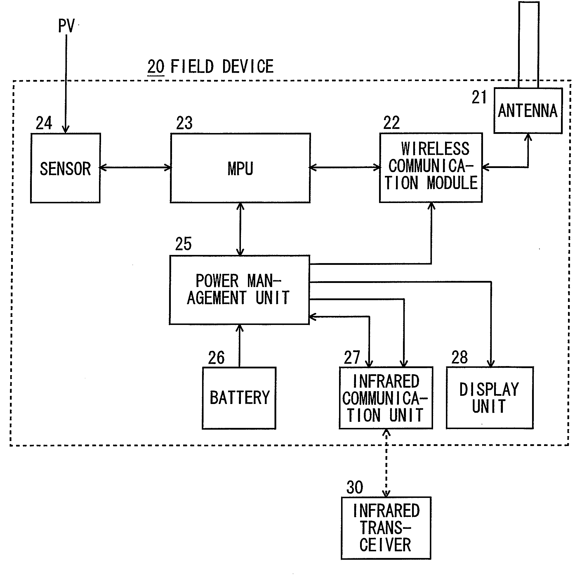
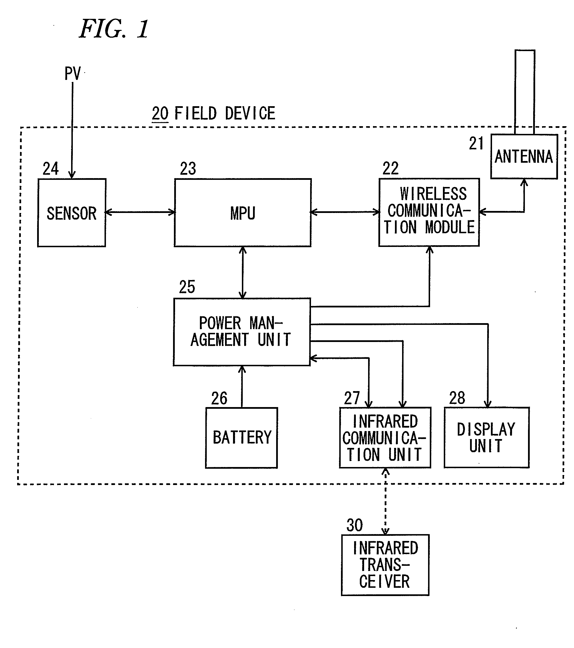
[0057]Exemplary embodiments of the present invention will be hereinafter described with reference to the drawings. FIG. 1 is a block diagram of a wireless field device 20 according to an embodiment of the invention. As shown in FIG. 1, the wireless field device 20 includes an antenna 21, a wireless communication module 22, an MPU 23, a sensor 24, a power management unit 25, a battery 26, an infrared communication unit 27, a display unit 28.

[0058]For example, an infrared transceiver 30 is a field device setting tool incorporating an infrared transmitter and receiver, and performs an infrared communication with the infrared communication unit 27.

[0059]The wireless communication module 22 is configured to exchange radio signals with the gateway 9 (see FIG. 8) via the antenna 21. A reception result of the wireless communication module 22 can be communicated to the MPU 23. In accordance with the instruction from the MPU 23, the wireless communication module 22 can send failure informatio...


PUM


Abstract

There is provided a wireless field device that performs a wireless communication with other filed devices in a wireless network through a gateway. The device includes: a battery incorporated in the field device to activate the field device; and a wireless communication module configured to exchange radio signals with the gateway to perform the wireless communication with said other field devices. When the filed device starts procedure for joining in the wireless network, firstly, the wireless communication module continuously accesses the gateway in a first period to receive an advertisement signal from the gateway, and when the wireless communication module fails to receive the advertisement signal in the first period, the wireless communication module intermittently accesses the gateway until receiving the advertisement signal from the gateway.

Description

[0001]This application claims priority from Japanese Patent Application No. 2010-149710, filed on Jun. 30, 2010, the entire contents of which are herein incorporated by reference.BACKGROUND[0002]1. Technical Field[0003]Embodiments described herein relate to a wireless field device.[0004]2. Related Art[0005]Conventionally, at places where a cable cannot be wired, for example, in water supply or sewer facilities such as manholes, a flowmeter that has a wireless communication function and serves as a wireless field device is attached to a pipe through which water flows.[0006]In collecting data or inspecting a facility, a worker receives data from a flowmeter in a manhole, for example, by performing a wireless communication with the flowmeter using a hand-held terminal which serves as a wireless communication device.[0007]Field devices include various devices having a communication function such as a pressure gauge, a differential pressure gauge, a thermometer, a level meter, and a flow...

Claims


Application Information

Patent Timeline
Patent Type & Authority Applications(United States)
IPC IPC(8): H04W88/02
CPCH04W52/0229Y02D30/70H04L41/0833
Inventor YOSHINO, HIROKIUEMURA, TOSHIMITSUSUGITANI, KUNIAKIFUJIMOTO, NAOYUKI
Owner YOKOGAWA ELECTRIC CORP
Why Eureka
Try Eureka