
Galvanic electrochemical cells utilizing taylor vortex flows

a technology of galvanic electrochemical cells and vortex flows, applied in the direction of indirect fuel cells, cell components, cell component details, etc., can solve the problems of electron and hole transfers during random momentary contact between freely-suspended faradaic and carbon particles, and the collision rate of either is limited to a small percentage of collisions

Active Publication Date: 2012-01-05
GLOBAL ENERGY SCI CALIFORNIA
View PDF0 Cites 29 Cited by
  • Summary
  • Abstract
  • Description
  • Claims
  • Application Information

AI Technical Summary

Benefits of technology

[0041]It is therefore a first advantage of the present invention to provide an improvement over earlier galvanic cells by providing new galvanic cells incorporating high-molar, non-Newtonian electrolytes.
[0042]A second advantage of this invention is to provide galvanic cells that incorporate TVF for use with high-molar galvanic, non-Newtonian electrolytes.
[0043]A third advantage of this invention is to provide galvanic cells that incorporate both TVF and CCF for use with high-molar galvanic, non-Newtonian electrolytes.
[0044]A fourth advantage of this invention is to provide high-molar galvanic, non-Newtonian electrolytes for use in galvanic cells.
[0045]A fifth advantage of this invention is to provide high-molar galvanic, non-Newtonian electrolytes containing carbon particles decorated with galvanic material flakes for use in galvanic cells
[0046]These advantages are more fully set forth in the following descriptions of preferred embodiments of this invention.BRIEF DESCRIPTIONS OF THE SEVERAL VIEWS OF THE DRAWINGS

Problems solved by technology

A few cells pump electrolyte, which introduces convection gradients that are many times those of other gradients; but, may cause energy dissipating turbulent flows as pumping rates increase.
However, electron and hole transfers during random momentary contact between freely-suspended faradaic and carbon particles while either are in mutual contact with the metal surface is limited to a small percentage of collisions.

Method used


Image

  • Galvanic electrochemical cells utilizing taylor vortex flows
  • Galvanic electrochemical cells utilizing taylor vortex flows
  • Galvanic electrochemical cells utilizing taylor vortex flows

Examples


first embodiment

Metal Hydride or Li-Ion Self Contained Battery

The Cell

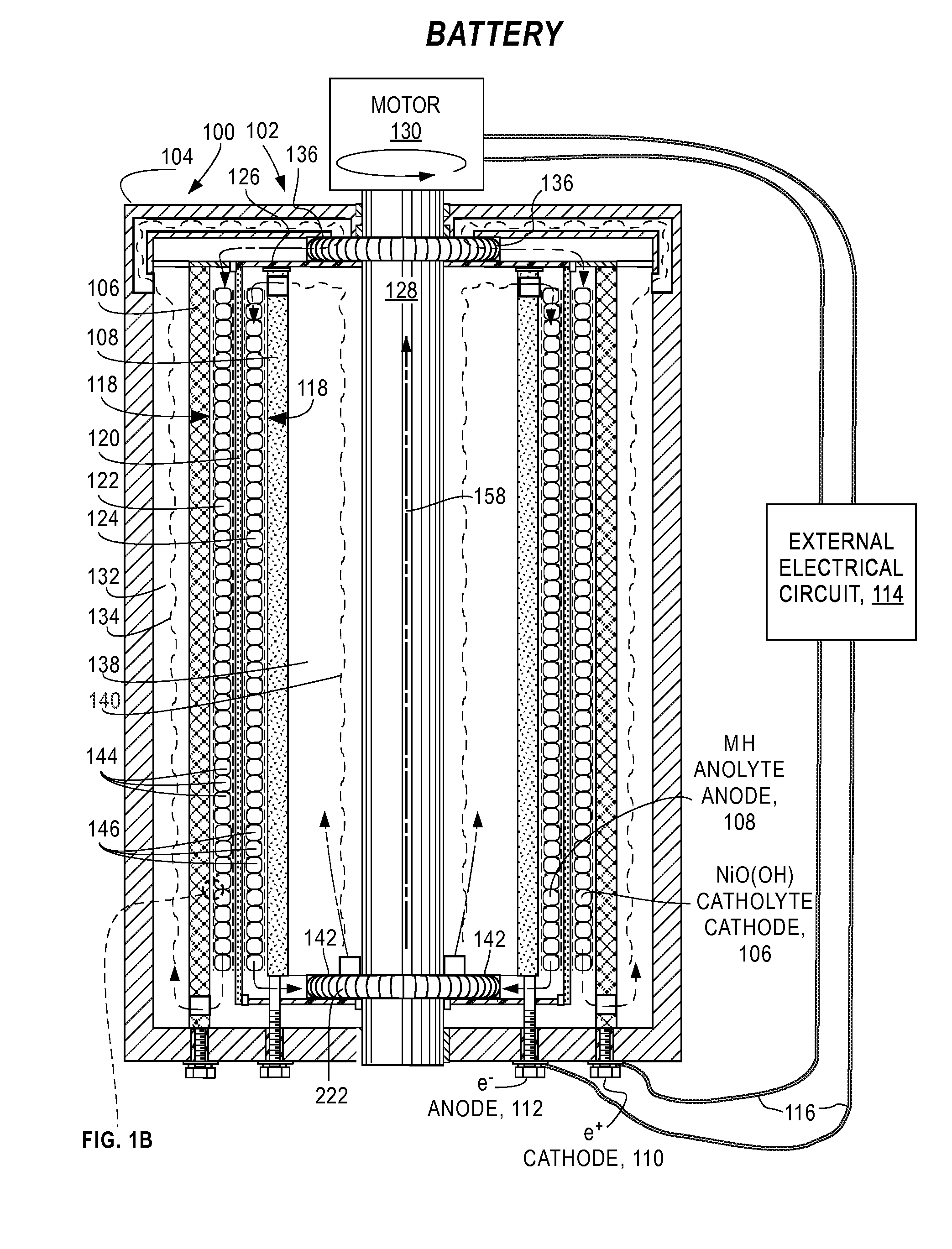
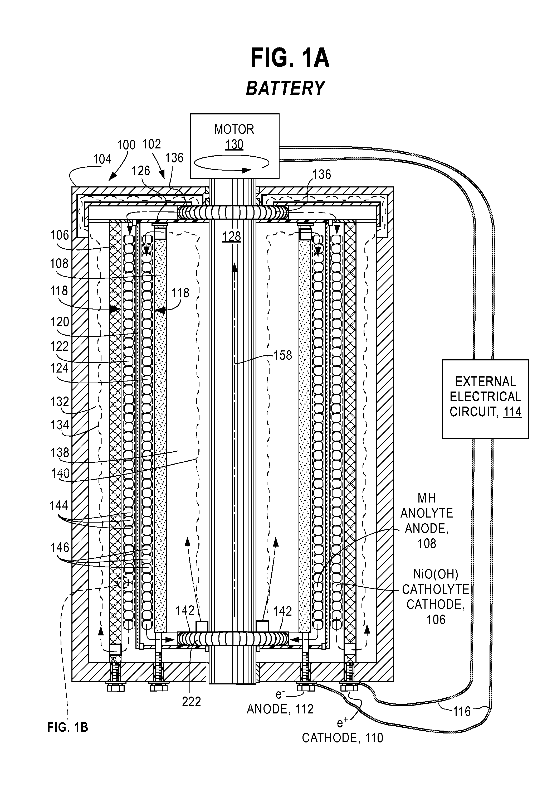
[0054]FIG. 1A and FIG. 1B are a cross-sectional views of essential features of a preferred embodiment of an electrochemical cell 100 of this invention configured as a metal hydride battery 102. The battery 102 comprises a case 104 containing an outer current collector 106 and an inner current collector 108 that are fixed to the case 104 and connected by positive terminal 110 (battery CATHODE) and negative terminal 112 (battery ANODE), respectively, to external electrical circuit 114 by conductors 116. In this embodiment, the current collectors 106, 108 are coaxial right-circular cylinders; however, these attributes are not a requirement and other cylinder-like geometries (e.g. elliptical, conical, hyperbolic, irregular, different axes) may be employed so long as the surfaces do not come in contact with each other.

[0055]A gap 118 between the current collectors 106 and 108 is divided by filter 120 into an outer electrolyte chamber ...

second embodiment

Flow Cells

The Cell

[0106]FIG. 5 is a cross-sectional view of essential features of a preferred embodiment of an electrochemical cell 500 of this invention configured as a redox flow cell 502. The flow cell 502 comprises a case 504 containing an outer current collector 506 and an inner current collector 508 that are fixed to the case 504 and connected by positive terminal 510 (battery CATHODE) and negative terminal 512 (battery ANODE), respectively, to external electrical circuit 514 by conductors 516. In this embodiment, the current collectors 506, 508 are coaxial right-circular cylinders; however, these attributes are not a requirement and other cylinder-like geometries (e.g. elliptical, conical, hyperbolic, irregular, different axes) may be employed so long as the surfaces do not come in contact with each other.

[0107]A gap 518 between the current collectors 506 and 508 is divided by filter 520 into an outer electrolyte chamber 522 and an inner electrolyte chamber 524. The filter 52...

third embodiment

Fuel Cells

The Cell

[0138]FIG. 6 is a cross-sectional view of essential features of a preferred embodiment of an electrochemical cell 600 of this invention configured as a fuel flow cell 602. The fuel cell 602 comprises a case 604 containing an outer current collector 606 and an inner current collector 608 that are fixed to the case 604 and connected by positive terminal 610 (cell CATHODE) and negative terminal 612 (cell ANODE), respectively, to external electrical circuit 614 by conductors 616. In this embodiment, the current collectors 606, 608 are coaxial right-circular cylinders; however, these attributes are not a requirement and other cylinder-like geometries (e.g. elliptical, conical, hyperbolic, irregular, different axes) may be employed so long as the surfaces do not come in contact with each other.

[0139]A gap 618 between the current collectors 606 and 608 is divided by filter 620 into an outer electrolyte chamber 622 and an inner electrolyte chamber 624. The filter 620 is al...


PUM


Abstract

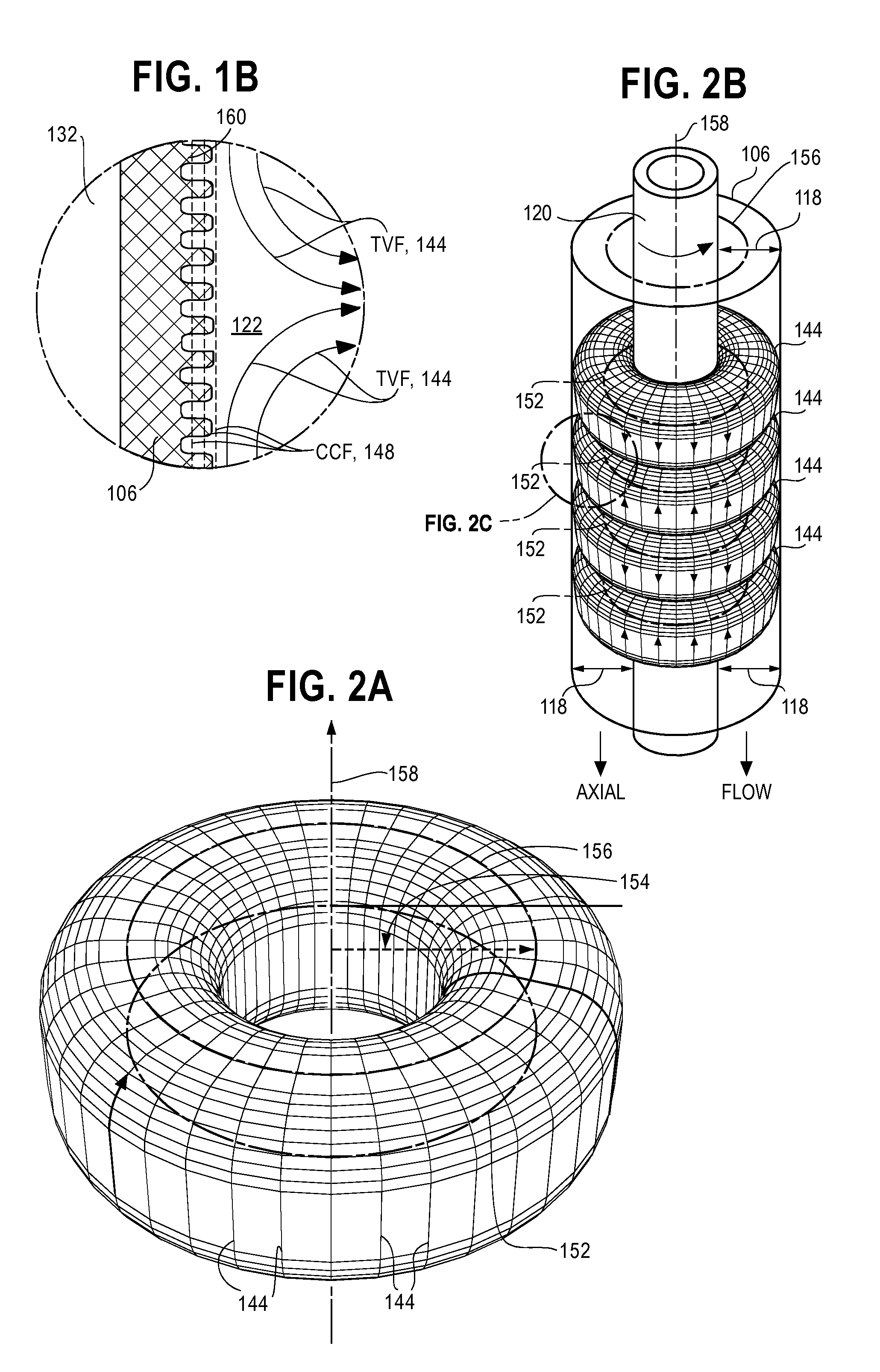
Electrochemical cells (100, 500, 600) for converting chemical energy into electrical energy, such as batteries (102), flow cells (502) and fuel cells (602) with a cylindrical rotating ion-permeable filter (120, 414, 520, 620) that generates Taylor Vortex Flows (144, 146, 404, 544, 546, 664, 666) and Circular Couette Flows (148, 150, 568, 570, 668, 670) in thixotropic catholytes and anolytes between a cylindrical current collector (106, 506, 606, 108, 508, 608) and the filter (120, 414, 520, 620) are disclosed.

Description

CROSS-REFERENCE TO RELATED APPLICATIONS[0001]This application is a continuation-in-part of U.S. patent application Ser. No. 13 / 194,049 of 29 Jul. 2011 that is a division of U.S. patent application Ser. No. 12 / 800,658 filed 20 May 2010, now U.S. Pat. No. 8,017,261 of 13 Sep. 2011, which claims the benefit of my U.S. Provisional Application No. 61 / 220,583 filed 26 Jun. 2009.[0002]This application, identified as Case A2, is related to the following applications of Halbert P. Fischel:[0003]Case A: Electrochemical Cells Utilizing Taylor Vortex Flows, Ser. No. 12 / 800,658 of 20 May 2010, now U.S. Pat. No. 8,017,261 of 13 Sep. 2011;[0004]Case A1: Electrochemical Cells Utilizing Taylor Vortex Flows, Ser. No. 13 / 194,049 of 29 Jul. 2011;[0005]Case B: Fuel Reformers Utilizing Taylor Vortex Flows, application Ser. No. 12 / 800,710 of 20 May 2010, now Publication No. US 2010 / 0330445 A1 of 30 Dec. 2010;[0006]Case C: Chemical Process Accelerator Systems Comprising Taylor Vortex Flows, application Ser...

Claims


Application Information

Patent Timeline
IPC IPC(8): H01M2/38H01M8/04
CPCH01M2/38H01M8/1011H01M8/20H01M4/70H01M10/00H01M10/0525Y02E60/528H01M6/00H01M8/00H01M8/004H01M12/06H01M12/08H01M10/345H01M50/70Y02E60/10Y02E60/50
Inventor FISCHEL, HALBERT
Owner GLOBAL ENERGY SCI CALIFORNIA
Learn More