Method For Control In A Process Control System Implemented In Part By One Or More Computer Implemented Run-Time Processes

Active Publication Date: 2012-01-05
ABB (SCHWEIZ) AG
View PDF8 Cites 52 Cited by
  • Summary
  • Abstract
  • Description
  • Claims
  • Application Information

AI Technical Summary

Benefits of technology

[0012]The principle advantage of the present invention is that it provides a solution where user interfaces of integrated applications can be integrated in a single system user interface without installing any code components from those applications. This is referred to as View Integration. The invention involves remote viewing, or sharing a view, and does not involve sharing an executable computer application or program.
[0013]View Integration, in meaning used in this description, is when the user interface (UI) of a non-core application, or extended application, is streamed to an integrated view in the control systems user interface (UI), using a technique similar in principle to the Windows service called Remote Desktop.
[0014]The integrated application runs in a separate computing process environment (sometimes referred to as a sandbox) and presents it

Problems solved by technology

A challenge with current approaches for user interface integration in a control system is that code components from the integrated applications execute in the same environment as components that are critical for the core functions of the

Method used


Image

  • Method For Control In A Process Control System Implemented In Part By One Or More Computer Implemented Run-Time Processes
  • Method For Control In A Process Control System Implemented In Part By One Or More Computer Implemented Run-Time Processes
  • Method For Control In A Process Control System Implemented In Part By One Or More Computer Implemented Run-Time Processes

Examples


Embodiment Construction

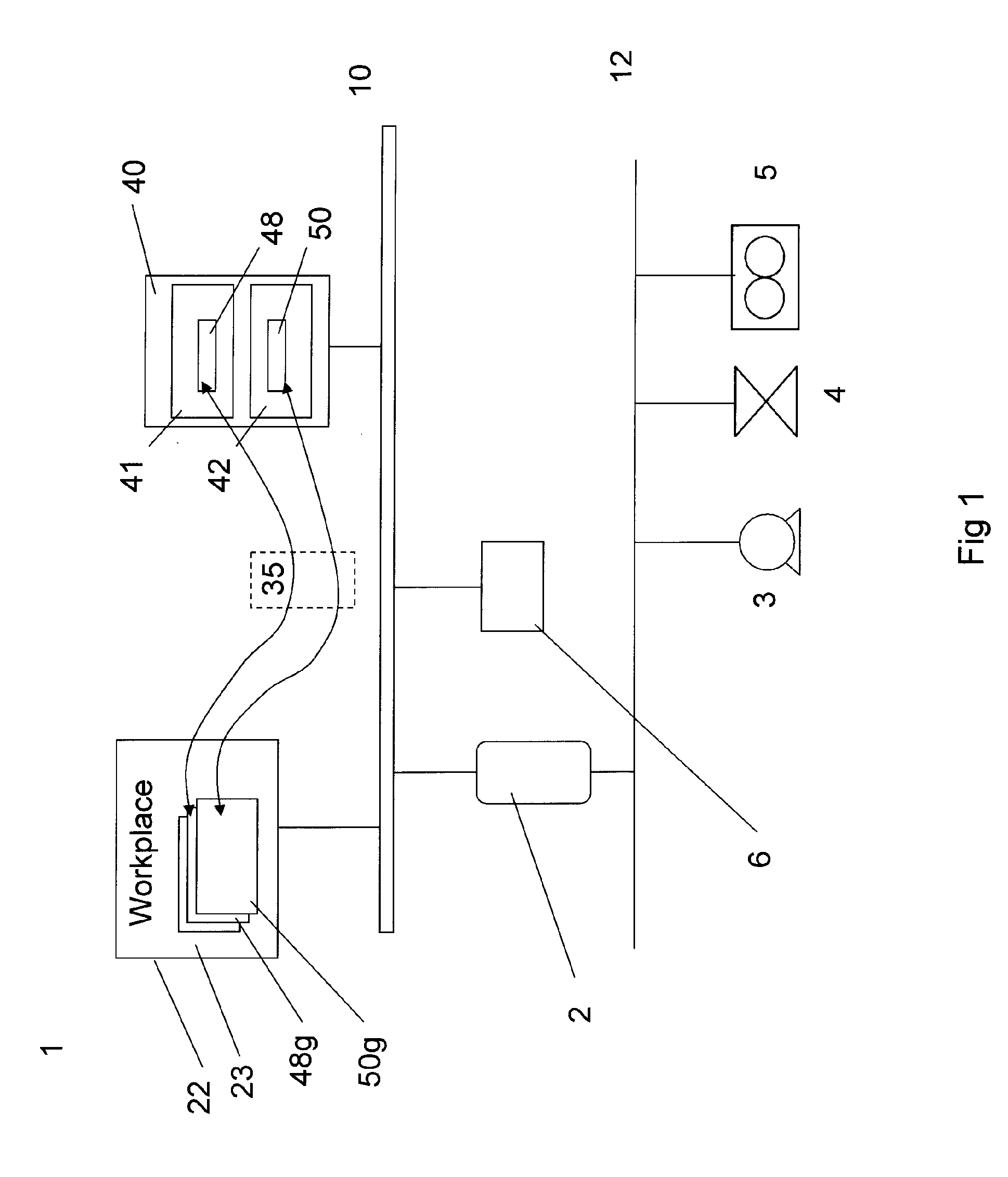
[0022]FIG. 1 shows a simplified diagram for a process control system. The system comprises controller 2, and server 6 running control functions, and business logic, for controlling the equipment and controls included in the industrial process. Many of these control functions are core processes that operate in real-time, and a number of them may be safety critical. The figure shows a process control system 1 with connected to equipment such as a motor 3, valve 4, field device such as a flow meter 5. The process control system 1 includes a data network 10, and a field bus 12. Parts of the data communications may be carried out by both wired and wireless links.

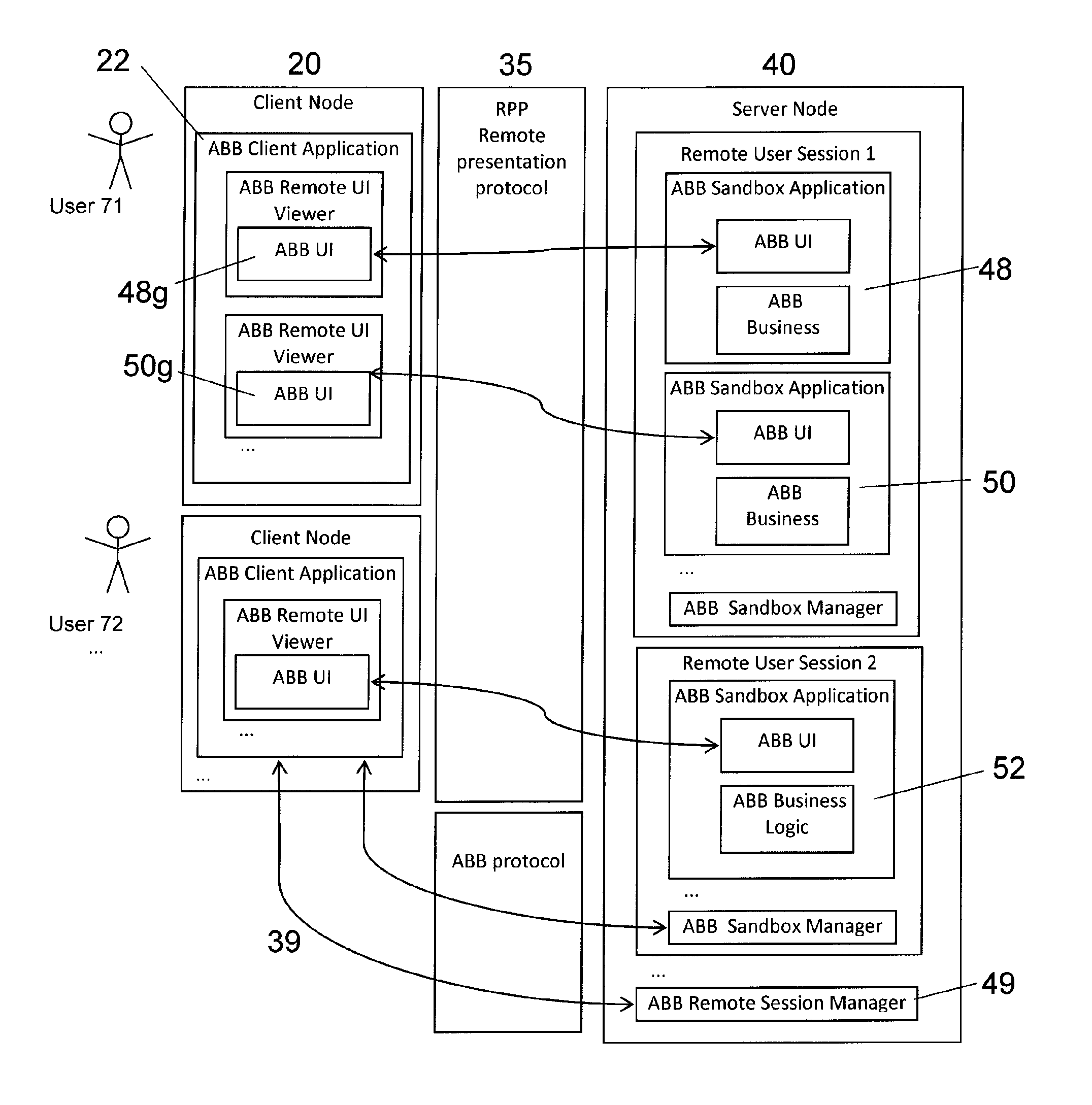
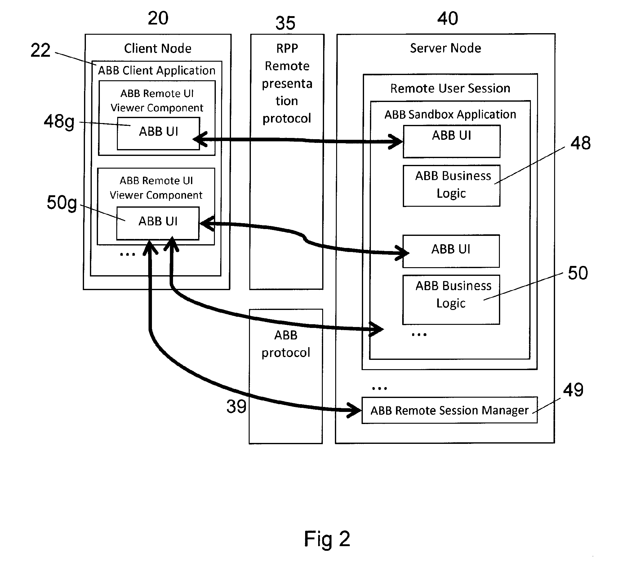
[0023]Connected to the process control system is a workstation (Workplace) which is arranged as a Client Node and running a Control System Client application 22 which provides a first graphic user interface (GUI) 23. This first graphic user interface (GUI) is an interface to a client application running business logic or core pro...


PUM


Abstract

A method for control in a process control system, where a graphical user interface of said process control system is arranged with graphic representations of one or more control objects for monitoring and/or control of a process or an equipment. The control system GUI is displayed by a control system client application on a computer or workstation. In addition, one or more applications for monitoring and/or controlling at least one said control object are run in a computing process environment separate from said process control system. No code components execute in the same processing space as that running the GUI for the process control system. Any flaw or error in the extended applications cannot affect the control system program controlling an industrial process in real-time. A control system and a computer program are also disclosed.

Description

CROSS-REFERENCE TO RELATED APPLICATIONS[0001]The present application is a continuation of pending International patent application PCT / EP2010 / 051767 filed on Feb. 12, 2010 which claims the benefit under 35 U.S.C. §119(e) of U.S. Provisional Patent Application Ser. No. 61 / 160,021, filed on Mar. 13, 2009. The content of all prior applications is incorporated herein by reference.FIELD OF THE INVENTION[0002]The present invention is concerned with an industrial control system graphic user interface. In particular it is concerned with a graphical user interface of a process control system used for monitoring and control purposes in an industrial installation.BACKGROUND OF THE INVENTION[0003]In computer based control systems for controlling manufacturing and process industries, such as chemical plants, oil refineries, pulp and paper mills, steel mills, etc., there is typically a need for integrating a wide range of different applications of different origin. In particular this integration ...

Claims


Application Information

Patent Timeline
IPC IPC(8): G06F15/16
CPCG05B19/4148H04L67/125G05B23/0267G06F9/452G05B2219/31457
Inventor HARDING, JEFFDAHLSTEDT, PETTERPAULY, THOMASOLSSON, JOAKIM
Owner ABB (SCHWEIZ) AG
Why Eureka
Try Eureka