
Filler coupling and corresponding receptacle and filling method

a technology of contaminated isolation valves and couplings, which is applied in the direction of water supply installations, fluid pressure control, packaging goods types, etc., can solve the problems of large leakage rate over the life of the product, large loss of sealing capacity in the sealing zone of the contaminated isolation valve, etc., and achieves a high level of protection and minimizes turbulence

Active Publication Date: 2012-01-12
LAIR LIQUIDE SA POUR LETUDE & LEXPLOITATION DES PROCEDES GEORGES CLAUDE
View PDF2 Cites 9 Cited by
  • Summary
  • Abstract
  • Description
  • Claims
  • Application Information

AI Technical Summary

Benefits of technology

[0018]Such an arrangement also makes it possible to improve the reliability and the safety of the filler system. Specifically, the dust-prevention valve guides and forces the incoming gas stream during filling when it travels downstream. The passageway ducts passing through the dust-prevention valve can notably make it possible to reduce the turbulence of the gas when filling. In this manner, the generated vibrations are also reduced. The convergence of the stream or streams passing through the dust-prevention valve notably makes it possible to accelerate the stream of gas and to concentrate it on a central zone of the passageway, notably at the opening of the seat (the upstream portion of the downstream isolation valve). This configuration makes it possible at least partly to save the valve spring from the filling gas stream. This guidance of the filling gas may also make it possible to direct the stream of gas toward the zone forming the seat for the downstream isolation valve, which promotes its being cleaned on each fill. This makes it possible to reduce the risks of leaks due to a dirty isolation valve seat.
[0032]Similarly, the movable dust-prevention valve can ensure an opening of the upstream of the coupling allowing the downstream isolation valve to be opened with the pressure of the filling gas (as a function of the pressures and setting of the valves).

Problems solved by technology

However, this protection is not usually sufficient because, when the dust-prevention valve is open, the filler connector that enters the filler coupling downstream of the dust-prevention valve can bring in particles.
Contamination of the isolation valve may cause a considerable leakage rate over the life of the product on which this filler coupling is installed.
This is explained by the fact that the sealing zone of the contaminated isolation valve (dust, particles etc.) loses a large proportion of its sealing capability.
This risk of intrusion of particles is increased when the filler coupling is vertical (filling from above).
This makes it possible to trap particles or dust upstream of the isolation valve but does not make it possible to actuate the opening of the isolation valve by mechanical contact (the filter in fact forming a mechanical barrier for a valve driver).
However, the upstream end of the isolation valve is then subject to contamination by particles or dust that can affect its sealing.

Method used


Image

  • Filler coupling and corresponding receptacle and filling method
  • Filler coupling and corresponding receptacle and filling method
  • Filler coupling and corresponding receptacle and filling method

Examples


Embodiment Construction

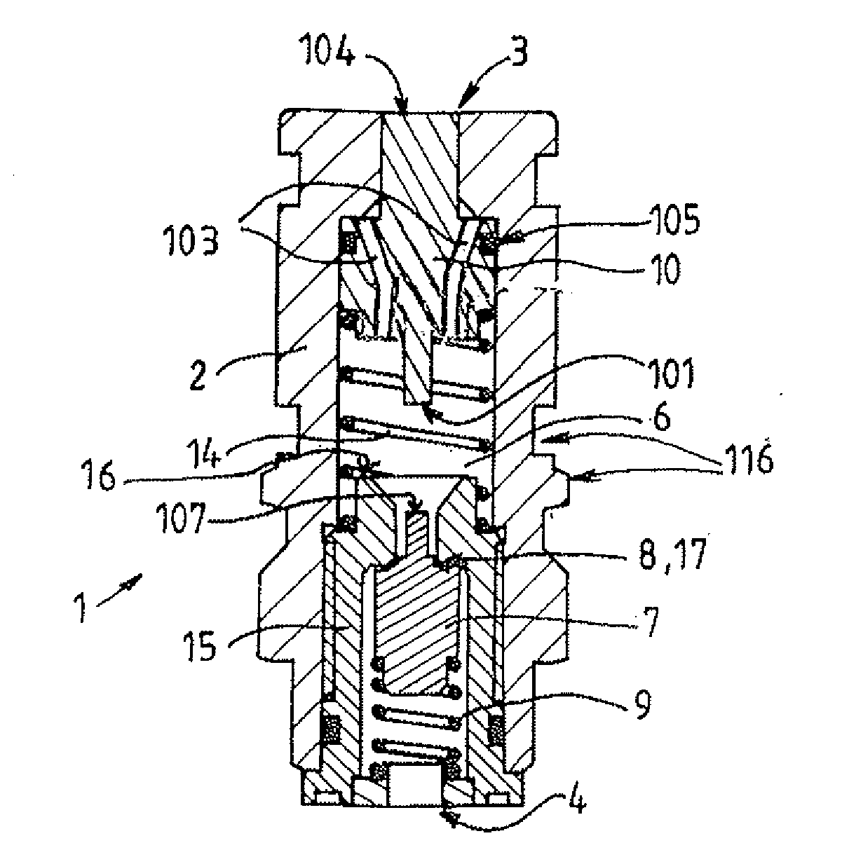
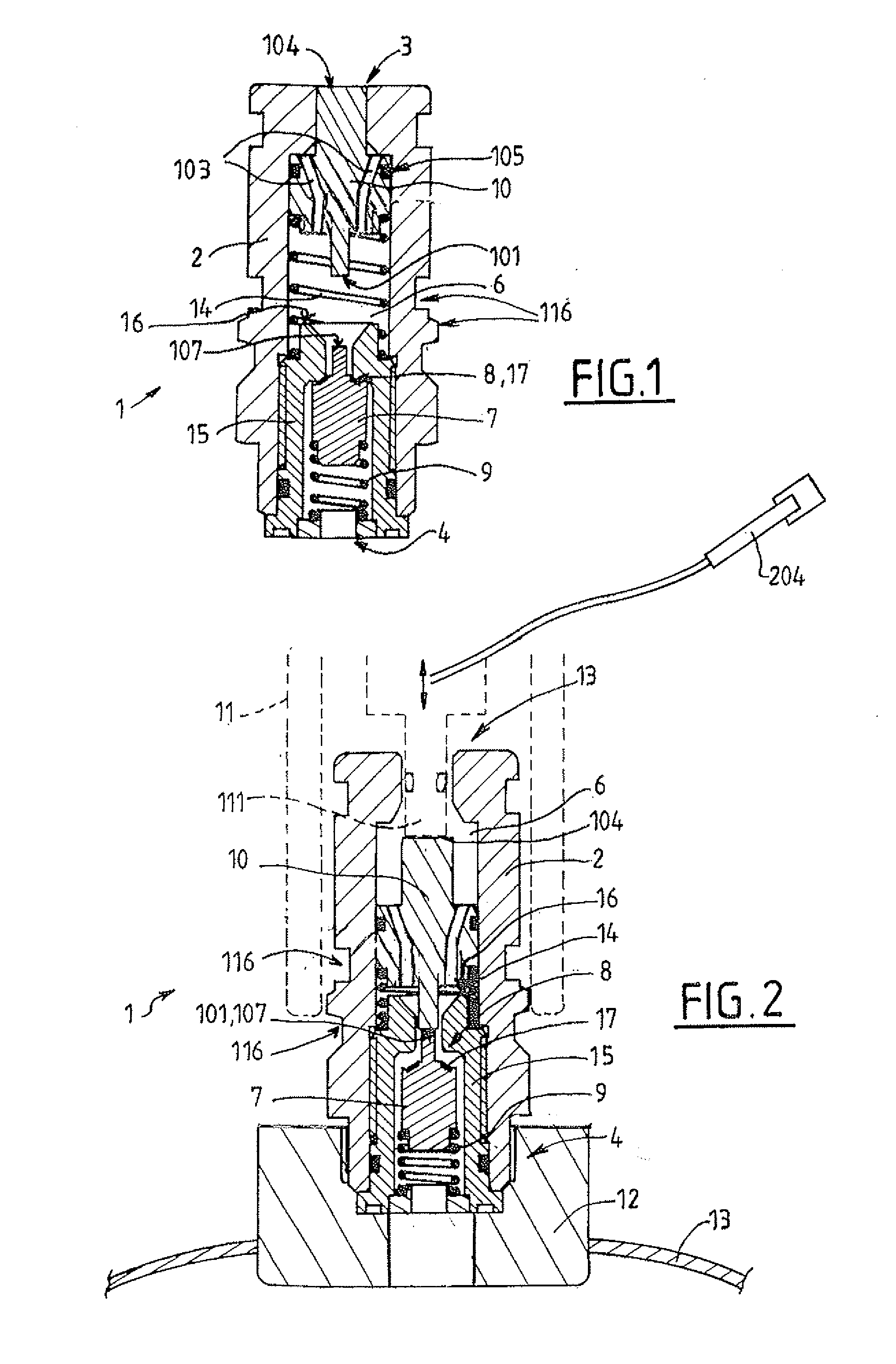
[0092]Now with reference to FIG. 1, the filler coupling 1 comprises a body 2, for example of generally cylindrical shape. The body 2 defines an internal filling circuit 6 between an upstream end 3 designed to be connected to a packaging connector and a downstream end 4 designed to be connected to a pressurized gas receptacle (via for example an internal circuit of a tap).

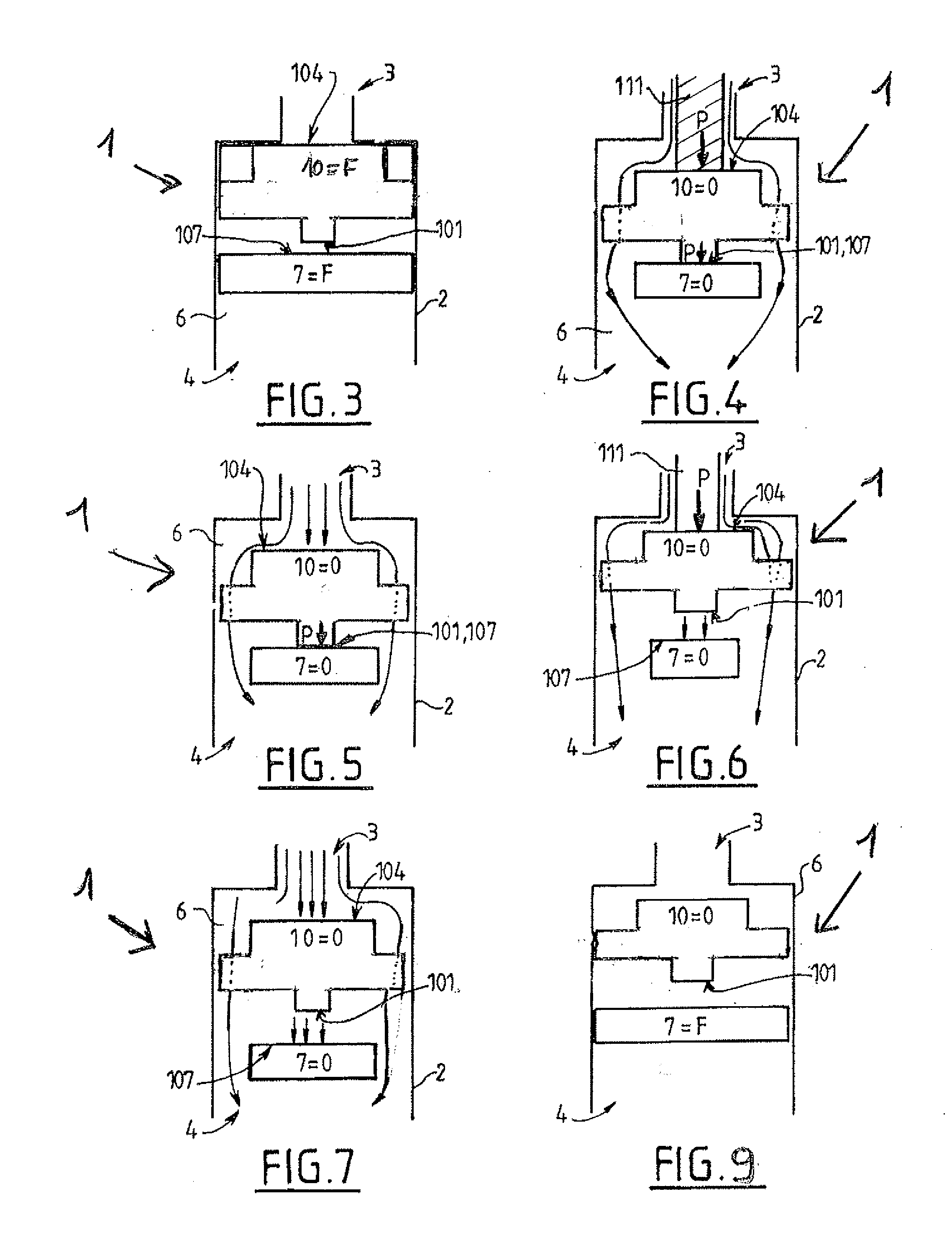
[0093]The upstream end 3 of the circuit 6 (and of the coupling 1) can be selectively closed by a dust-prevention valve 10 which can move in the body 2 of the coupling.

[0094]The dust-prevention valve 10 can be selectively moved in the body 2 (preferably in translation) between an upstream position for closing the upstream end 3 of the circuit 6 and a downstream position for opening the circuit upstream end 3. Preferably, the dust-prevention valve 10 is moved to its upstream position by a return member 14, for example a spring such as a compression spring.

[0095]Preferably, in the upstream position for closing the upst...


PUM

PropertyMeasurementUnit
mechanicalaaaaaaaaaa
opening forceaaaaaaaaaa
pressureaaaaaaaaaa

Abstract

A filler coupling comprising an isolation valve that can move relative to a seat between an upstream closing position and a downstream opening position, said isolation valve being moved to its upstream position by a return member, the coupling also comprising a dust-prevention valve placed upstream of the isolation valve, said dust-prevention valve comprising a downstream end and being able to move relative to the body between an upstream closing position and a downstream opening position, said dust-prevention valve being moved to its upstream position by a return member, characterized in that the dust-prevention valve can be moved selectively downstream either:in a first determined downstream position opening the upstream end in which the downstream end of the dust-prevention valve does not push the upstream end of the isolation valve, or ina second determined downstream position opening the upstream end, in which the downstream end of the dust-prevention valve pushes an upstream end of the movable isolation valve in order to move the isolation valve by contact to its downstream open position, and in that the dust-prevention valve comprises one or more passageways for guiding at least a portion of the fluid stream traveling from upstream to downstream through the body of said dust-prevention valve.

Description

CROSS-REFERENCE TO RELATED APPLICATIONS[0001]This application claims the benefit of priority under 35 U.S.C. §119 (a) and (b) to French Application No. 10 55605, filed Jul. 9, 2010, the entire contents of which are incorporated herein by reference.BACKGROUND[0002]1. Field of the Invention[0003]The present invention relates to a filler coupling, a tap, a pressurized fluid receptacle and a filling method using such a coupling.[0004]The invention relates more particularly to a filler coupling for a pressurized gas receptacle designed to interact with a packaging connector in order to allow said receptacle to be filled, the coupling comprising a body defining an internal filler circuit between an upstream end designed to be connected to a packaging connector and a downstream end designed to be connected to a receptacle, the coupling comprising an isolation valve that can move relative to a seat between an upstream position for closing the circuit and a downstream position for opening th...

Claims


Application Information

Patent Timeline
Patent Type & Authority Applications(United States)
IPC IPC(8): F17D3/00
CPCF16K1/303F16K1/308F17C13/04F17C2205/0323F17C2205/0335B67D7/02F17C2205/0382F17C2205/0385F17C2205/0394F17C2223/0123F17C2260/036F17C2205/0341F17C2227/048Y10T137/7838Y10T137/87917F17C2205/0344
Inventor FRENAL, ANTOINEPISOT, PHILIPPEMANSCOURT, CYRIL
Owner LAIR LIQUIDE SA POUR LETUDE & LEXPLOITATION DES PROCEDES GEORGES CLAUDE
Features
  • Generate Ideas
  • Intellectual Property
  • Life Sciences
  • Materials
  • Tech Scout
  • Unparalleled Data Quality
  • Higher Quality Content
  • 60% Fewer Hallucinations
Learn More