Eureka AIR delivers breakthrough ideas for toughest innovation challenges, trusted by R&D personnel around the world.

Tail Wheel Transporter

a technology of transporter and tail wheel, which is applied in the direction of transportation items, vehicle maintenance, vehicle-manoeuvring devices, etc., can solve the problems of loss of control of the aircraft while in flight, high cost, and heavy invention of eckert, and achieves easy steering, constant manual force, and maintain the effect of li

Active Publication Date: 2012-01-12
PERRY DANIEL S
View PDF5 Cites 6 Cited by
  • Summary
  • Abstract
  • Description
  • Claims
  • Application Information

AI Technical Summary

Benefits of technology

[0012]Another object and feature of the present invention is to provide a tail wheel transporter that is lightweight and does not require the application of constant manual force to maintain lift or balance. Another object and feature of the present invention is to provide a tail wheel transporter that is easy to steer. Another object and feature of the present invention is to provide a tail wheel transporter that is adaptable to tail wheels of various widths. Another object and feature of the present invention is to provide a tail wheel transporter that can be manufactured in various sizes and strengths for retaining tail wheels and aircraft of various masses. Another object and feature of the present invention is to provide a tail wheel transporter that can be adapted to lift tail wheels of various diameters. Another object and feature of the present invention is to provide a tail heel transporter that is inexpensive to manufacture and ship.
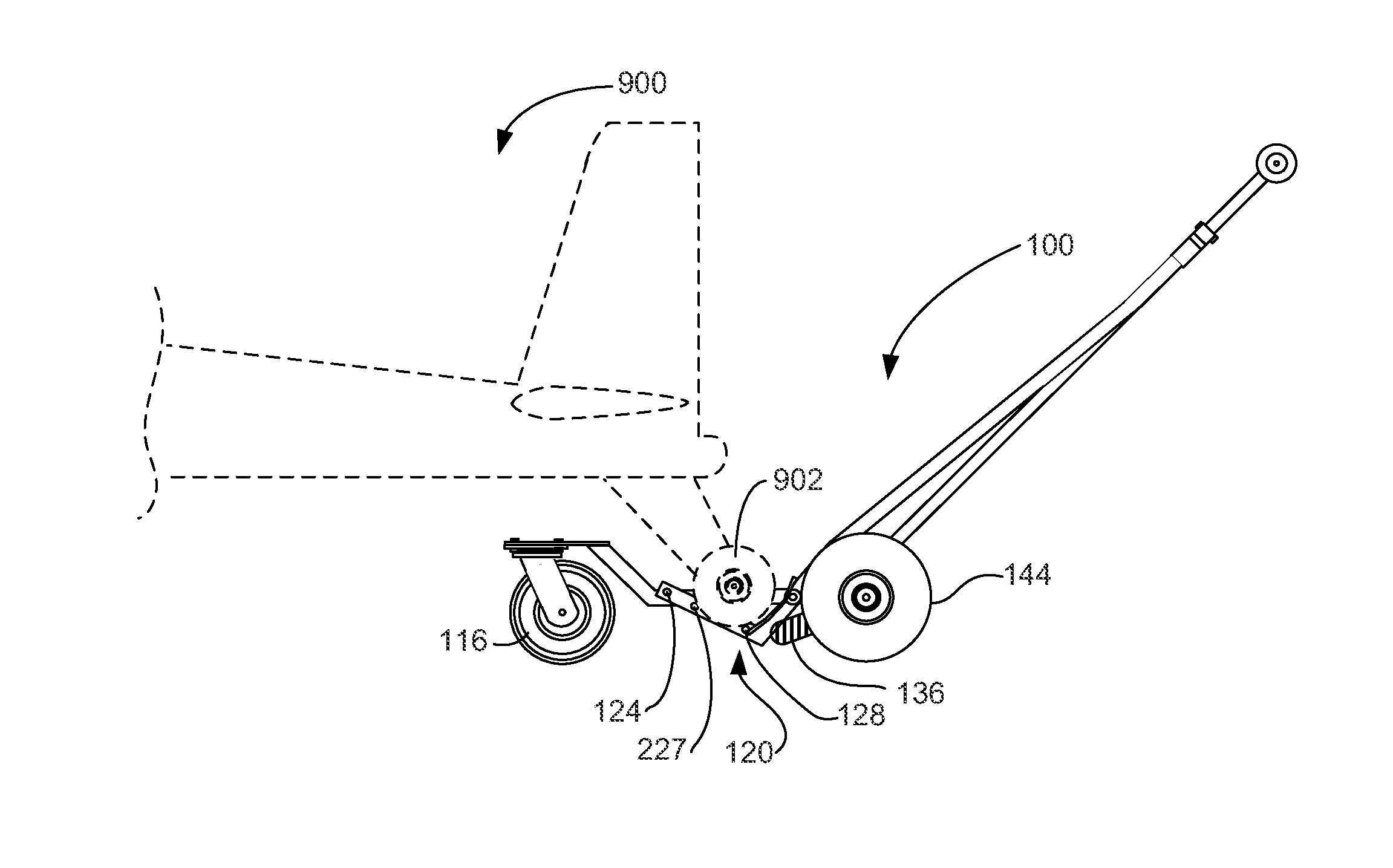
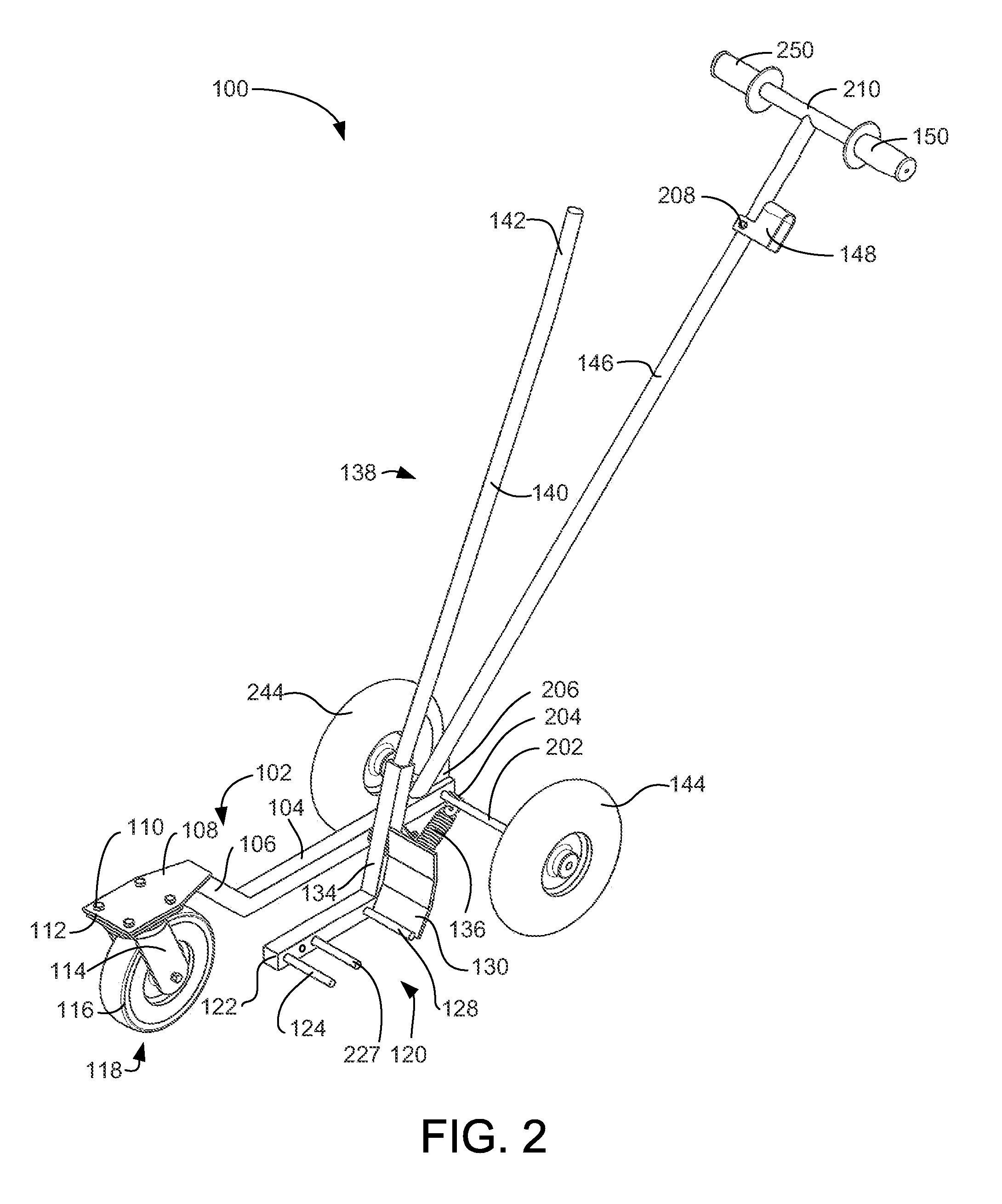
[0014]In accordance with a preferred embodiment hereof, the present invention provides a tail wheel transporter with a single-beam chassis having a tricycle wheel configuration and an elongated handle extending from the single beam for manual control and towing. The single beam is offset on the rear two-wheel axle to support a substantially L-shaped lever that is side mounted on the chassis. The short foot of the “L” supports one or more studs for initially engaging the underside of a tail wheel from the side. At least one of the studs may be moveable. The long arm of the “L”, or lifting arm, is manually operated to lift the tail wheel off the ground. In the lifted position, the tong arm of the “L” is latched to the elongated handle so that constant manual force to maintain lift is not required. The tail wheel is received between the front and rear axles and below the height of the axles, so no manual force is required to maintain balance during operation. The front wheel of the tricycle configuration is a caster to make steering easy. An adjustable biasing mechanism biases the lifting arm toward the non-lifted position.

Problems solved by technology

Depending on the weight and design of the tail wheel aircraft, this may be a strenuous task.
Pushing or pulling of these control surfaces for the purpose of ground movement is generally not recommended and could cause damage that could result in loss of control of the aircraft while in flight.
As a motorized system, Eckert's invention is very heavy, very complex, and expensive.
Being motorized and battery powered, Iles' invention is heavy and expensive.

Method used


Image

  • Tail Wheel Transporter
  • Tail Wheel Transporter
  • Tail Wheel Transporter

Examples


Embodiment Construction

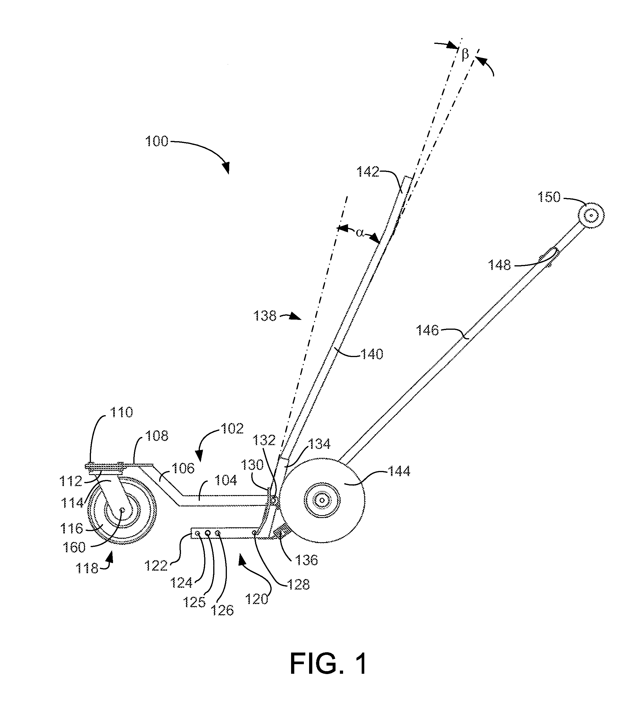
[0032]FIG. 1 is a side elevation view illustrating an exemplary tail wheel transporter 100, according to a preferred embodiment of the present invention. Main frame 102 includes horizontal frame member 104 and angled frame extension 106. Horizontal frame member 104 supports elongated handle 146, axle 202 (see FIG. 2), and pivot 132. Angled frame extension 106 supports caster attachment plate 108. Main frame 102 is preferably made of substantially rigid material, such as steel or aluminum. In various embodiments, various other materials may be used. For example, in an embodiment where weight is at a premium, such as a tail wheel transporter 100 designed to be transported in an aircraft, Boron-epoxy composite may be used. Those of skill in the art, illuminated by the present disclosure, will be aware of materials that are appropriate for various unique applications.

[0033]Caster attachment plate 108 is preferably welded to angled extension 106. In an alternate embodiment, main frame 10...


PUM


Abstract

A tail wheel transporter with a single-beam chassis in a tricycle carriage and a towing arm extending from the single beam for towing and steering. The single beam is offset on the rear two-wheel axle to pivotably support a lifting arm, or lever, that is side mounted on the chassis. The short foot of the “L” supports one or more adjustable studs for initially engaging the underside of a tail wheel from the side. The lifting arm is manually operated to lift the tail wheel off the ground. In the lifted position, the lifting arm is latched to the towing arm so that constant manual force to maintain lift is not required. The tail wheel is received between the front and rear axles and exerts force below the height of at least some of the axles, so no manual force is required to maintain balance during operation.

Description

RELATED APPLICATIONS[0001]This application claims the benefit of U.S. Provisional Patent Application 61 / 362,342 filed Jul. 8, 2010 by the same inventor.FIELD OF THE INVENTION[0002]This invention relates to a device for moving an aircraft having tail wheel while the aircraft is on the ground. The invention further relates to a lever jack on a dolly.BACKGROUND[0003]In general aviation, it is sometimes necessary to move aircraft on an aircraft hanger floor or on a tarmac without powering up the aircraft engine. For aircraft equipped with tail wheels (hereinafter “tail wheel aircraft”), it is generally preferred to move the aircraft by grasping the tail and then pushing, pulling, and / or turning the aircraft. Depending on the weight and design of the tail wheel aircraft, this may be a strenuous task. The tail of a tail wheel aircraft is the location of several of the aircraft's control surfaces. Pushing or pulling of these control surfaces for the purpose of ground movement is generally ...

Claims


Application Information

Patent Timeline
Patent Type & Authority Applications(United States)
IPC IPC(8): B62D53/04
CPCB60S13/00B62B3/0606B62B3/0625B62B3/0643B62B3/12B62B2202/90B62B2203/10B64F1/22B66F1/00
Inventor PERRY, DANIEL S.
Owner PERRY DANIEL S
Why Eureka
Eureka Blog
Learn More