Probe head of probe card and manufacturing method of composite board of probe head

Inactive Publication Date: 2012-01-12
MICROELECTRONICS TECH INC
View PDF12 Cites 10 Cited by
  • Summary
  • Abstract
  • Description
  • Claims
  • Application Information

AI Technical Summary

Benefits of technology

[0005]One aspect of the present invention is to provide a probe head of a vertical probe card, so as to stabilize the

Problems solved by technology

However, the friction coefficient of the ceramic guide plate, with especially the friction coefficient of the bottom guide plate, is larger, so that during the electrical testing of the electronic device under test 4 b

Method used


Image

  • Probe head of probe card and manufacturing method of composite board of probe head
  • Probe head of probe card and manufacturing method of composite board of probe head
  • Probe head of probe card and manufacturing method of composite board of probe head

Examples


Embodiment Construction

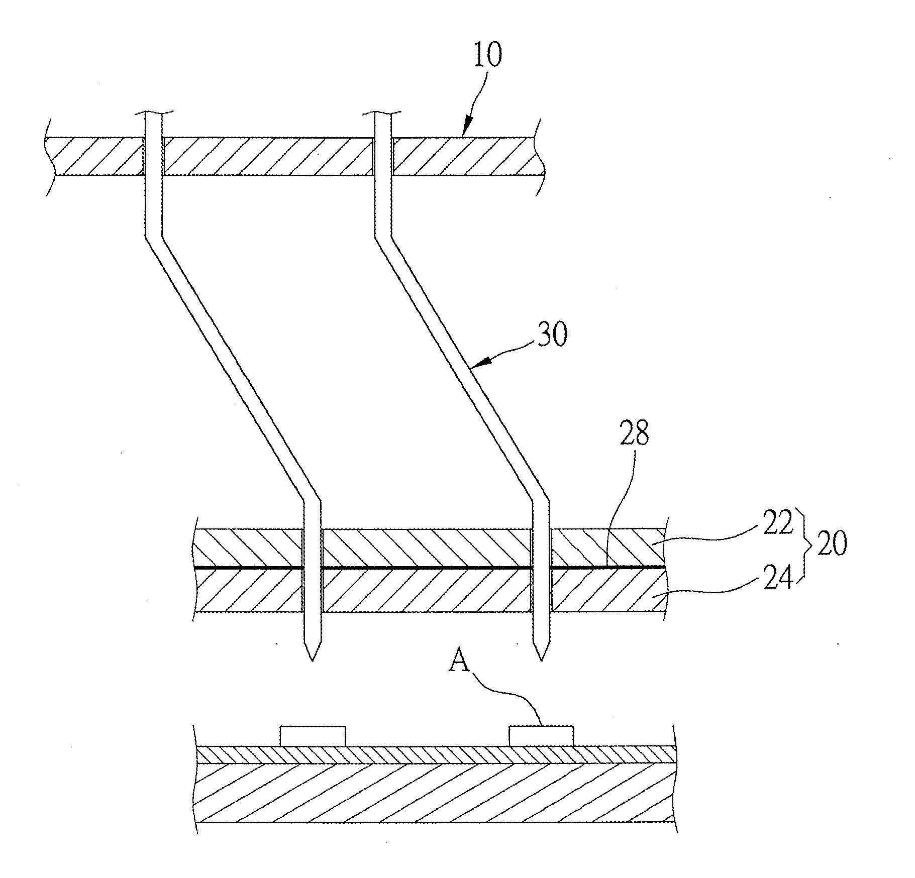
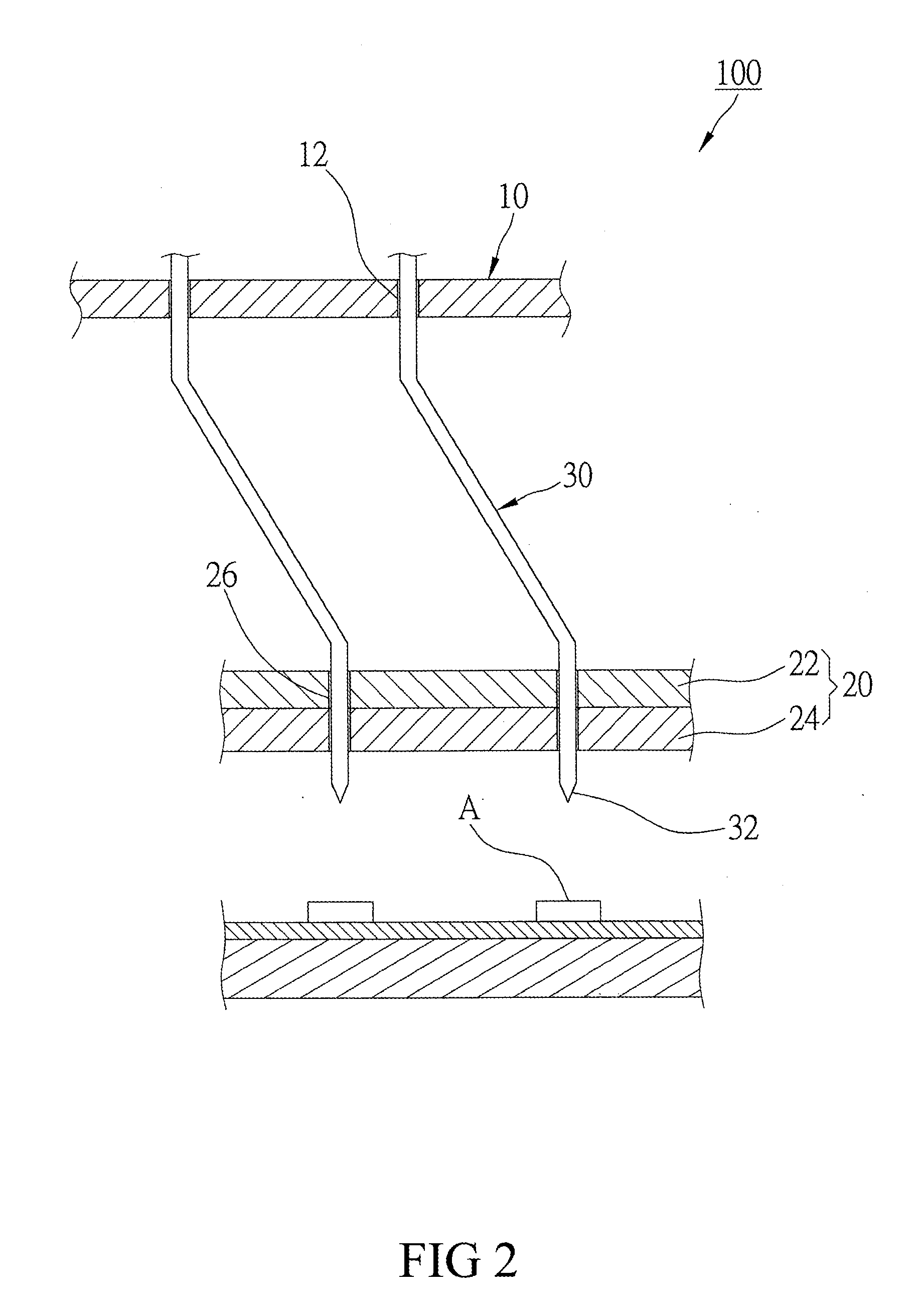
[0015]FIG. 2 is a diagram of a probe head of a vertical probe card according to an embodiment of the present invention. The probe head 100 includes a guide plate 10, a composite board 20, and a plurality of probe pins 30. The guide plate 10 has a plurality of through holes 12.

[0016]The composite board 20 is disposed under the guide plate 10 at a pre-determined distance. The composite board 20 includes a first board layer 22 and a second board layer 24. The first board layer 22 faces the guide plate 10. A plurality of through holes 26 is disposed on the composite board 20. The through holes 26 are passed all the way through the first board layer 22 and the second board layer 24. According to the embodiment, a manufacturing method of the composite board 20 includes the following steps. At first, the first board layer 22 and the second board layer 24 are laminated together. Then, a joining process is performed so as to join the first board layer 22 and the second board layer 24 togethe...


PUM

PropertyMeasurementUnit
Thicknessaaaaaaaaaa
Diameteraaaaaaaaaa
Frictionaaaaaaaaaa

Abstract

A probe head of vertical probe card and a manufacturing method of a composite board thereof are provided. The probe head includes guide plate, composite board, and probe pin. The composite board includes first board layer and second board layer which are laminated together by joining operation. The composite board further includes through hole which is made by drilling and passed all the way through the first board layer and the second board layer. The friction coefficient of the first board layer is less than that of the second board layer, and the thermal expansion coefficient of the second board layer is less than that of the first board layer. The probe pin is penetrated all the way through the through hole of the composite board. By this, friction between the probe pin and composite board is reduced so as to stabilize the position of the probe pin.

Description

FIELD OF THE INVENTION[0001]The invention relates to a probe card for electrical testing, especially relates to a probe head of a vertical probe card and a manufacturing method of a composite board thereof.BACKGROUND OF THE INVENTION[0002]A vertical probe card is generally used in testing of dies of flip chip packages, and in the parallel testing of multi dies surrounding a pad. As shown in FIG. 1, a probe head of a vertical probe card is disposed under a circuit board (not shown), so that the top end and the bottom end thereof are electrically connect to an electronic device under test and the circuit board, respectively. The probe head includes a top guide plate 1, a bottom guide plate 2, and a plurality of probe pins 3. The probe pins 3 are penetrated through the top guide plate 1 and the bottom guide plate 2, so as to be supported and positioned. Due to the densely disposed electronic devices under test, the probe pins 3 are thereby arranged tightly. During the testing process, ...

Claims


Application Information

Patent Timeline
IPC IPC(8): G01R1/067H05K3/22B32B38/04
CPCY10T156/1057G01R31/2889G11B5/455H05K2201/10378
Inventor CHEN, MING-CHIFAN, HORNG-KUANGSHEN, MAO-FACHUEH, MING-CHULIU, BANG-SHUNLIN, CHE-WEI
Owner MICROELECTRONICS TECH INC
Why Eureka
Try Eureka