Magnetic recording head capable of monitoring light for thermal assist

a magnetic recording and light source technology, applied in the field of thermally assisted magnetic recording heads, can solve the problems of difficult monitoring installation system, little has been done to monitor light output from the light source for thermal assist, and little has been done to prevent such increase in air resistance, so as to achieve good thermally assisted magnetic recording, good thermally assisted effect, and good

Active Publication Date: 2012-01-12
TDK CORPARATION
View PDF3 Cites 46 Cited by
  • Summary
  • Abstract
  • Description
  • Claims
  • Application Information

AI Technical Summary

Benefits of technology

[0018]In the thermally-assisted magnetic recording head according to the present invention, the photodetector section which enables constant monitoring of light output from the light source is provided, as described above. Accordingly, feedback adjustment of light output of the light source, which emits light for thermal assist, can be accomplished. Further, light output from the light source can be controlled by the adjustment in response to changes in the light output due to environmental influence or changes in the light output over time to stabilize the intensity of light for thermal assist with which a magnetic recording medium is irradiated. Consequently, a region of the magnetic recording medium where data is to be written can be properly and stably heated. Therefore, a good thermally-assisted magnetic recording can be accomplished.
[0019]Furthermore, the photodetector section is formed inside the unit substrate and the light-receiving portion is located on the source-installation surface side of the unit substrate so that the light-receiving portion can receive laser light emitted from the rear light-emission center of the light source. Accordingly, the rear light-emission center and the light-receiving portion can be located sufficiently close to each other so that light output from the light source can be monitored with a higher efficiency. In addition, since the monitoring system is contained inside the unit substrate in the light source unit, the light source unit has a less irregular general outline. This can avoid increase of air resistance of the the...

Problems solved by technology

However, it is difficult to install a system for monitoring the light in an element-integration surface of a head for thermal assist together with an optical system that propagates the light for thermal assist, because of a li...

Method used


Image

  • Magnetic recording head capable of monitoring light for thermal assist
  • Magnetic recording head capable of monitoring light for thermal assist
  • Magnetic recording head capable of monitoring light for thermal assist

Examples


Embodiment Construction

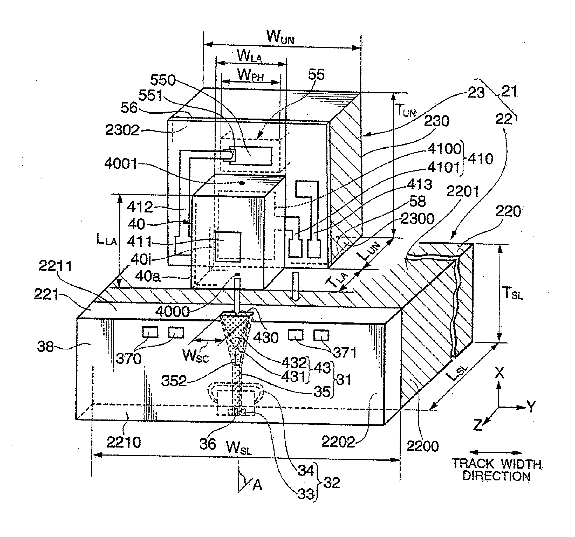
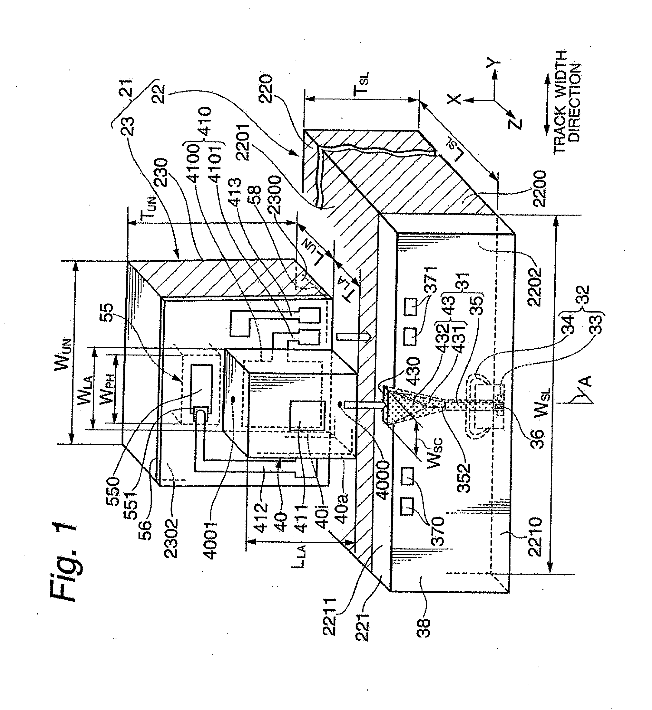
[0038]FIG. 1 shows a perspective view illustrating one embodiment of a thermally-assisted magnetic recording head according to the present invention.

[0039]As shown in FIG. 1, a thermally-assisted magnetic recording head 21 is constituted by aligning and joining a light source unit 23, which includes a laser diode 40 as a light source and a photodiode section 55 as a photo-detecting part, and a slider 22, which includes an optical system 31.

[0040]The slider 22 includes: a slider substrate 220 having an air bearing surface (ABS) 2200 processed so as to provide an appropriate flying height; and a head element part 221 that includes an optical system 31 and is formed on an element-integration surface 2202 that is perpendicular to and adjacent to the ABS 2200. While, the light source unit 23 includes: a unit substrate 230 having an joining surface 2300; a laser diode 40 as a light source provided on a source-installation surface 2302 that is perpendicular to and adjacent to the joining s...


PUM


Abstract

Provided is a thermally-assisted magnetic recording head in which a slider including an optical system is joined with a light source unit. The light source unit comprises: a unit substrate including a joining surface joined with the slider and a source-installation surface adjacent to the joining surface; a light source provided in the source-installation surface and emits light for thermal assist; and a photodetector section formed inside the unit substrate, a light-receiving portion of the photodetector section for receiving light emitted from a rear light-emission center being located on the source-installation surface side. The light source unit includes the photodetector section that enables constant monitoring of light output from the light source. Accordingly, feedback adjustment of the light output can be accomplished. Further, since the rear light-emission center and the light-receiving portion can be located sufficiently close to each other, the light output can be monitored with a higher efficiency.

Description

BACKGROUND OF THE INVENTION[0001]1. Field of the Invention[0002]The present invention relates to a thermally-assisted magnetic recording head constituted by joining a light source unit including a light source for emitting light used for thermally-assisted magnetic recording and a slider. The present invention further relates to a head gimbal assembly (HGA) including the head, and to a magnetic recording apparatus including the HGA.[0003]2. Description of the Related Art[0004]With the explosion in the use of the Internet in these years, a huge amount of data that are incommensurably larger than ever are stored and used on computers such as servers and information processing terminals. This trend is expected to further grow at an accelerated rate. Under these circumstances, demand for magnetic recording apparatuses such as magnetic disk apparatuses as mass storage is growing, and the demand for higher recording densities of the magnetic recording apparatuses is also escalating.[0005]...

Claims


Application Information

Patent Timeline
IPC IPC(8): G11B11/00
CPCG11B5/314G11B2005/0021G11B5/6088
Inventor SHIMAZAWA, KOJITANAKA, KOSUKEKOMURA, EIJIHONDA, TAKASHI
Owner TDK CORPARATION
Why Eureka
Try Eureka