System and method for transmission, processing, and rendering of stereoscopic and multi-view images

a multi-view image and transmission system technology, applied in the field of digital image processing systems, can solve the problems of significant cost, significant resolution degradation of prior art methods, and unviewable packed frames of older 2d televisions, and achieve the effect of reducing bandwidth and reducing bandwidth

a multi-view image and transmission system technology, applied in the field of digital image processing systems, can solve the problems of significant cost, significant resolution degradation of prior art methods, and unviewable packed frames of older 2d televisions, and achieve the effect of reducing bandwidth and reducing bandwidth

US20120008672A1Inactive Publication Date: 2012-01-12CHEYTEC TECH LLC

Image

  • System and method for transmission, processing, and rendering of stereoscopic and multi-view images
  • System and method for transmission, processing, and rendering of stereoscopic and multi-view images
  • System and method for transmission, processing, and rendering of stereoscopic and multi-view images

Examples


Embodiment Construction

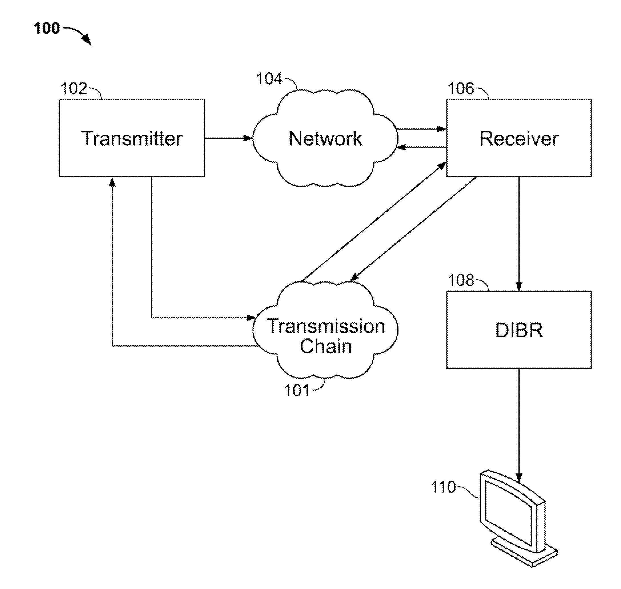
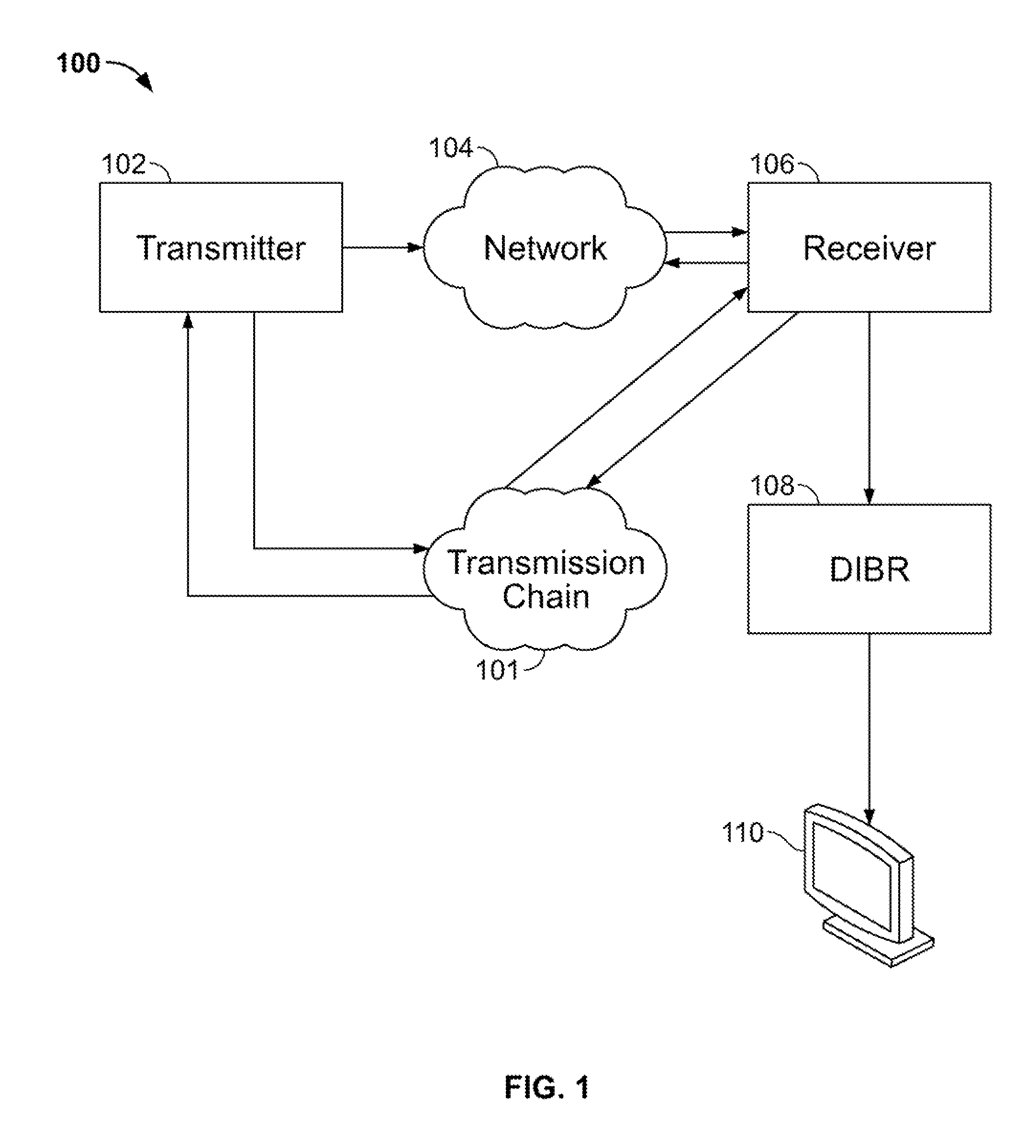
[0039]The present invention relates to a computer implemented image processing method and system for transmitting and receiving three-dimensional (3D) images. FIG. 1 depicts a block diagram of an exemplary 3D digital processing system 100, according to an embodiment of the present invention. The system 100 includes a computer-implemented receiver 102, a computer implemented transmitter 104, an optional depth-image-based rendering (DIBR) module 108 to be described hereinbelow, and an optional display 110. The system 100 does not include but employs a network 104 communicatively connected to the transmitter 102 and the receiver 104. The transmitter 102 receives 3D stereoscopic image data comprising color data (e.g., RGB, YUV, etc.) from a transmission chain 101 or generates the 3D stereoscopic image data within the transmitter 102. The transmitter 102 reduces bandwidth depth information (i.e., the Z channel) of the 3D stereoscopic image data at low or no incremental bandwidth cost, wi...


PUM


Abstract

A digital image processing system takes color plus Z channel data as input, preprocesses, decimates, and codes the Z channel in-band as digital watermark data embedded within the color data prior to encoding and transmission. A second digital image processing system receives, decodes, and extracts the decimated Z channel data before applying statistical regularization to restore a full-resolution Z channel prior to depth-image-based rendering.

Description

CROSS-REFERENCE TO RELATED APPLICATIONS[0001]This application claims the benefit of U.S. Provisional Patent Application No. 61 / 362,134 filed Jul. 7, 2010, the disclosure of which is incorporated herein by reference in its entirety.FIELD OF THE INVENTION[0002]The present invention relates generally to digital image-processing systems for the transmission and reception of depth information along with color information (e.g., RGB data), and more particularly, to a method and a digital image-processing system for receiving and using depth information and color information transmitted by a first digital image-processing system to render one or more three-dimensional (3D) views (e.g., stereoscopic or auto-stereoscopic views).BACKGROUND OF THE INVENTION[0003]Three-dimensional (3D) video and image transmission systems and 3D television (3D-TV) in particular have gained market acceptance in recent years. In order to present a 3D stereoscopic image to a viewer according to prior art systems, ...

Claims


Application Information

Patent Timeline
12 Jan 2012
Publication
US20120008672A1
IPC
H04N11/02
CPC
G06T1/0028; H04N13/0007; H04N13/0011; H04N13/0048; H04N13/0059; H04N13/0275; G06T2201/0202; H04N19/00757
Inventors
GADDY, WILLIAM L.; SERAN, VIDHYA