Power supply device

Active Publication Date: 2012-01-12
YAZAKI CORP +1
View PDF3 Cites 43 Cited by
  • Summary
  • Abstract
  • Description
  • Claims
  • Application Information

AI Technical Summary

Benefits of technology

[0022]As described above, since the present invention includes the positioning unit and the guide unit, the cell assembly and the plate are positioned by the positioning unit and the plurality of connecting members are guided to the positions where the connecting members respectively come into contact with the corresponding positive electrodes and negative electrodes by the guide unit. Accordingly, the plate can be simply attached to the prescribed position of the cell assembly. Further, the plurality of connecting members can be assuredly attached to the positive electrodes and the negative electrodes by an operation at one time and an assembly work can be simplified.
[0023]Further, since a plurality of bosses and the plurality of holes into which the plurality of bosses are inserted are provided, when the plurality of bosses are respectively inserted into the plurality of corresponding holes, the cell assembly and the plate are positioned. Accordingly, the plate can be simply attached to the prescribed position of the cell assembly and the assembly work can be simplified.
[0024]Further, since the guide unit is the pair of contact pieces having the space therebetween which is provided so as to be gradually larger than the space between the positive electrode and the negative electrode as the guide unit comes nearer to the positive electrode and the negative electrode, the positive electrode and the negative electrode can be assuredly located between the pair of contact pieces. Accordingly, the plurality of connecting members can be assuredly attached to the positive electrodes and the negative electrodes by the operation at one time and the assembly work can be simplified.
[0025]Further, since the plate includes the main body part, the pair of outer side parts and the connecting part that connects the main body part to the one pair of outer side parts, the main body part and the pair of outer side parts are respectively displaced relative to the cell assemb

Problems solved by technology

However, since a plurality of connecting members needs to be attached to the cel

Method used


Image

  • Power supply device
  • Power supply device
  • Power supply device

Examples


Embodiment Construction

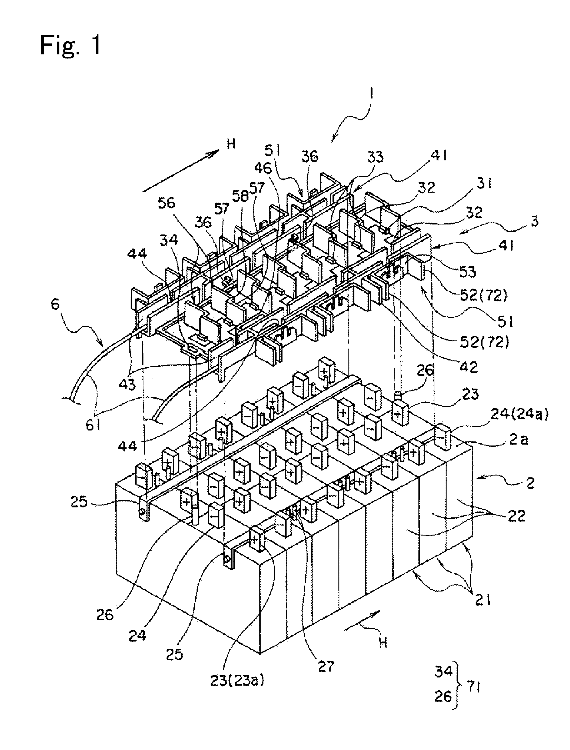
[0067]Now, a power supply device 1 according to a first embodiment of the present invention will be described below by referring to FIGS. 1 to 9. The power supply device 1 according to the first embodiment of the present invention is mounted on a hybrid vehicle that is driven by the driving forces of both an internal combustion engine and an electric motor or an electric motor vehicle that is driven by the driving force of the electric motor.

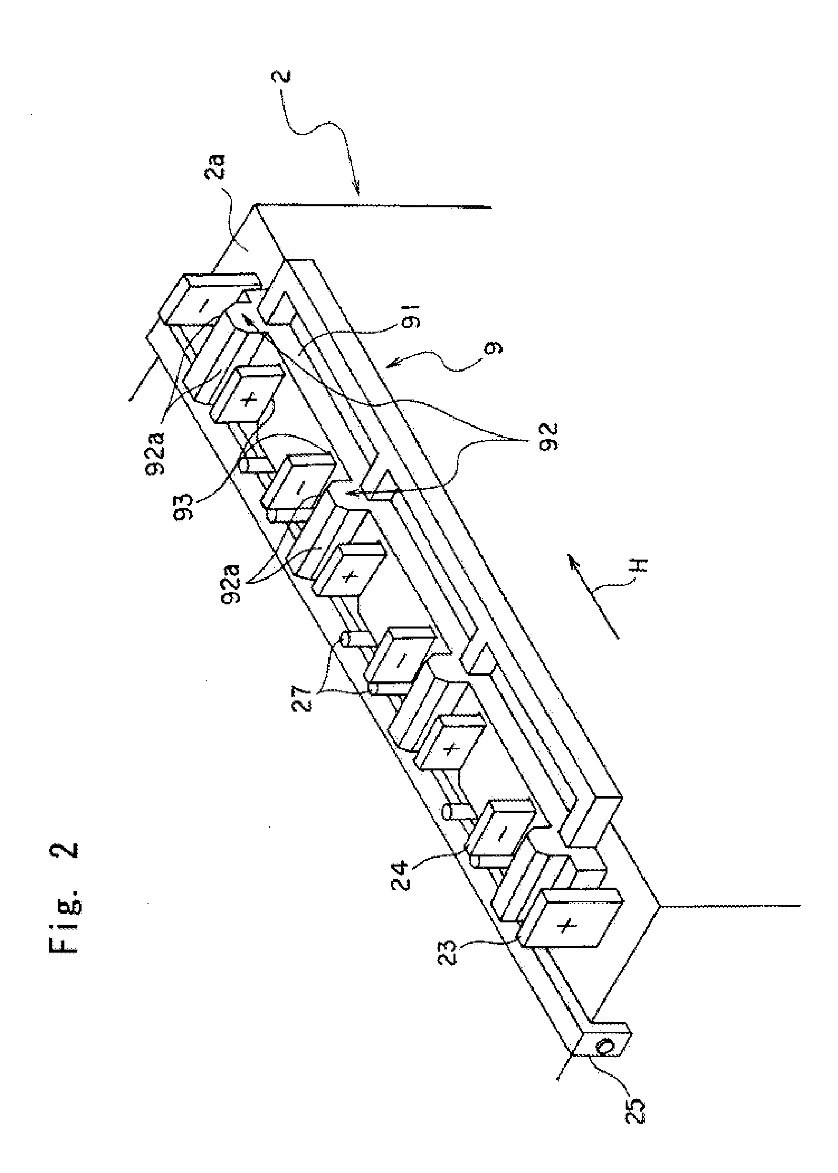
[0068]As shown in FIG. 1, the power supply device 1 includes a cell assembly 2, a plurality of first bus bars 51 (corresponding to connecting members), a plurality of second bus bars 56 and a plate 3. The cell assembly 2 has a plurality of cells 21 provided with positive electrodes (refer them as to anodes, hereinafter) 23 at one ends and negative electrodes (refer them to as cathodes, hereinafter) 24 at the other ends. The plurality of first bus bars 51 and the plurality of second bus bars 56 connect the anodes 23 of the one cells 21 to the cat...


PUM


Abstract

A power supply device, which is simply assembled and in which a cell assembly and a measuring section are freely inserted and detached, is provided. A power supply device 1 includes a cell assembly 2, a plurality of first bus bars 51, a plate 3 to which the plurality of bus bars 51 are attached. The plate is overlapped on the cell assembly 2. The cell assembly 2 has a plurality of cells 21 respectively including positive electrodes 23 at one ends and negative electrodes 24 at the other ends. The first bus bars 51 connect the positive electrodes 23 of the one cells 21 to the negative electrodes 24 of the other cells 21 of the cell assembly 2 which are mutually adjacent when the plate 3 is overlapped or overlaid on the cell assembly 2. The power supply device 1 includes a positioning unit 71 that relatively positions the cell assembly 2 to the plate 3 and a guide unit 72 that guides the plurality of first bus bars 51 to positions where the first bus bars 51 connect the respectively corresponding positive electrodes 23 to the negative electrodes 24 when the plate 3 is attached to the cell assembly 2.

Description

TECHNICAL FIELD[0001]The present invention relates to a power supply device mounted on a hybrid motor vehicle that travels by the driving forces of both an internal combustion engine and an electric motor or an electric motor vehicle that travels by the driving force of the electric motor.BACKGROUND ART[0002]On the hybrid motor vehicle driven by the driving forces of the internal combustion engine and the electric motor or the electric motor vehicle driven by the driving force of the electric motor, the power supply device is mounted and the power supply device serves to charge and discharge electric energy. Such a power supply device includes a cell assembly configured by a plurality of cells. In order to obtain a desired voltage, the plurality of cells are connected together in series. As the cell, a nickel hydrogen cell or a lithium ion cell is employed that is smaller and lighter, and higher in its supply voltage than the nickel hydrogen cell.[0003]In the above-described power s...

Claims


Application Information

Patent Timeline
IPC IPC(8): H01M2/06H01M6/42H01M50/209H01M50/264H01M50/505H01M50/569
CPCH01M2/206H01M2/1077Y02E60/10H01M50/209H01M50/505H01M50/264H01M50/569
Inventor IKEDA, TOMOHIROSHOJI, TAKAOYANAGIHARA, SHINICHIICHIKAWA, YOSHIAKIOGASAWARA, SHIGEYUKIMEGURO, KAZUHISAFUKAO, YASUYOSHIKATAYAMA, JUNTA
Owner YAZAKI CORP
Why Eureka
Try Eureka