

Fresnel Zone Fat Ray Tomography
a technology of fat ray tomography and fresnel zone, which is applied in the field of seismic data processing, can solve the problems of not having a fat ray technique specially designed, unstable velocity inversion, and uncertainty about the reliability of the final velocity model
Active Publication Date: 2012-01-12
EXXONMOBIL UPSTREAM RES CO
View PDF1 Cites 16 Cited by
- Summary
- Abstract
- Description
- Claims
- Application Information
AI Technical Summary
Problems solved by technology
In addition, such terms are usually not related to the physics of the problem, and therefore create uncertainty about the reliability of the final velocity model.
However up to the present time there has not been any fat ray technique especially designed to apply to reflection images and at the same time containing the appropriate physics of the reflection imaging problem.
For most imaging problems in reflection imaging, the velocity model is much more complex, and therefore new techniques are needed.
Their methods are primarily analytical, and do not address the computational issues faced in typical reflection imaging situations.
This approach has considerable potential advantages; however it typically requires very intensive computation especially for 3D processing which is the major application of velocity analysis methods.
However their fat rays do not cover the physically correct zone in space, and therefore can be viewed as a way of improving the stability of the calculation without actually affecting the resolving power of the method.
Method used
View moreImage
Smart ImageViewing Examples

Examples
example
[0052]FIGS. 12A-D show a comparison of the performance of the present method on a test model, with the axes representing depth and lateral distance. FIG. 12A shows the actual velocity test model; FIG. 12B shows the starting velocity model; FIG. 12C shows the result of using conventional thin ray tomography which is approximately the same as using a narrow band version of the present method, not summing over frequencies. FIG. 12D shows the result with the present method. There is clear improvement in resolution of the target.
Login to View More PUM
 Abstract
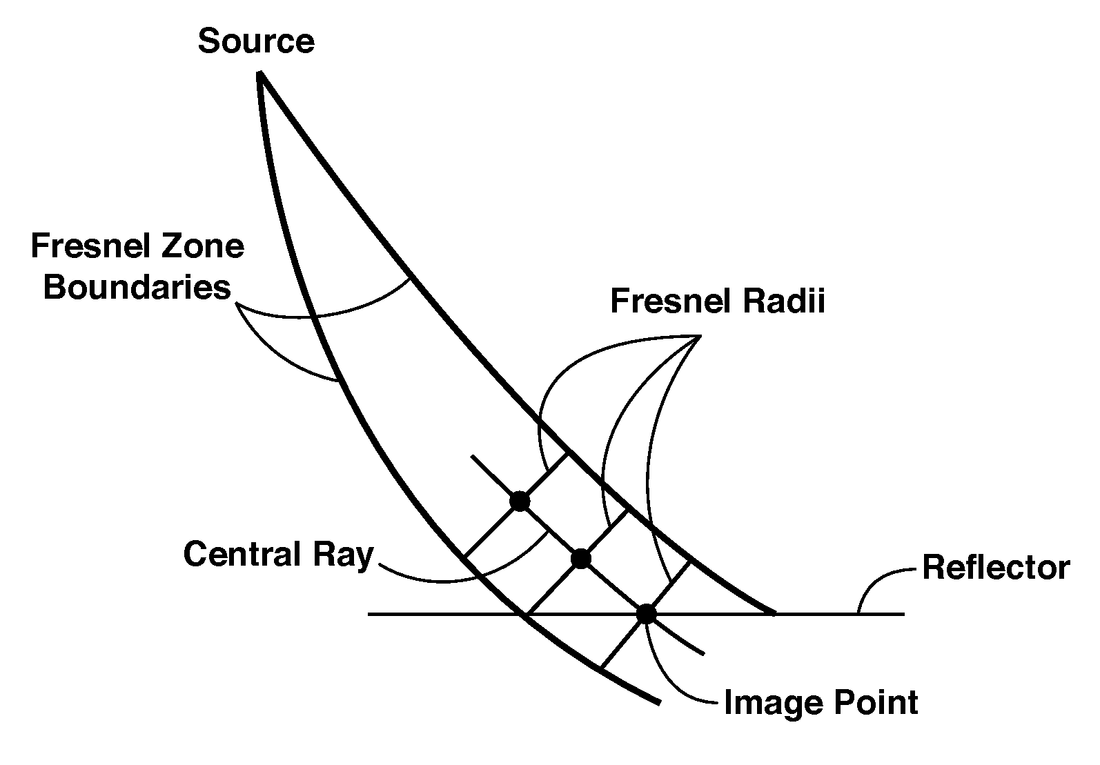
A stable method for using fat-ray tomography to determine a high-resolution velocity model of the subsurface from seismic data (71). The velocity model (72) may be used in migrating the seismic data (76) to image the subsurface. Rays are traced from a subsurface reflection point to surface source and receiver locations (73), using Fresnel zone construction methods (74) that honor correct initial conditions, with the Fresnel radius being a function of velocity.
Description
CROSS-REFERENCE TO RELATED APPLICATION[0001]This application claims the benefit of U.S. Provisional Patent Application 61 / 362,519, filed Jul. 8, 2010, entitled FRESNEL ZONE FAT RAY TOMOGRAPHY, the entirety of which is incorporated by reference herein.FIELD OF THE INVENTION[0002]The invention relates generally to the field of geophysical prospecting, and more particularly to seismic data processing. Specifically, the invention pertains to solving the problem of how to determine velocities in the subsurface for use in seismic migration.BACKGROUND OF THE INVENTION[0003]Migration of seismic data (moving reflectors in a subsurface image to their true depths by data processing) requires making some estimate of the acoustic velocity which normally varies throughout the subsurface region of interest. In this context, “velocity” normally means the velocity and also any anisotropy parameters included in the velocity model. It is well known that migration results depend on the assumed velocity...
Claims
Login to View More Application Information
Patent Timeline
 Patent Type & AuthorityApplications(United States)
IPC IPC(8): G01V1/28
CPCG01V1/303
InventorWINBOW, GRAHAM A.SUN, HONGCHUAN
OwnerEXXONMOBIL UPSTREAM RES CO