
Solar Heat Collector

a heat collector and solar energy technology, applied in the direction of solar heat devices, solar-ray concentration, moving/orienting solar heat collectors, etc., can solve the problems of large convective loss, large area, limited capacity to heat the exchanger fluid to very elevated temperatures, etc., and achieve the effect of reducing the loss of conveying and efficient cooling

Inactive Publication Date: 2012-01-19
LIEVRE LAURIER
View PDF38 Cites 7 Cited by
  • Summary
  • Abstract
  • Description
  • Claims
  • Application Information

AI Technical Summary

Benefits of technology

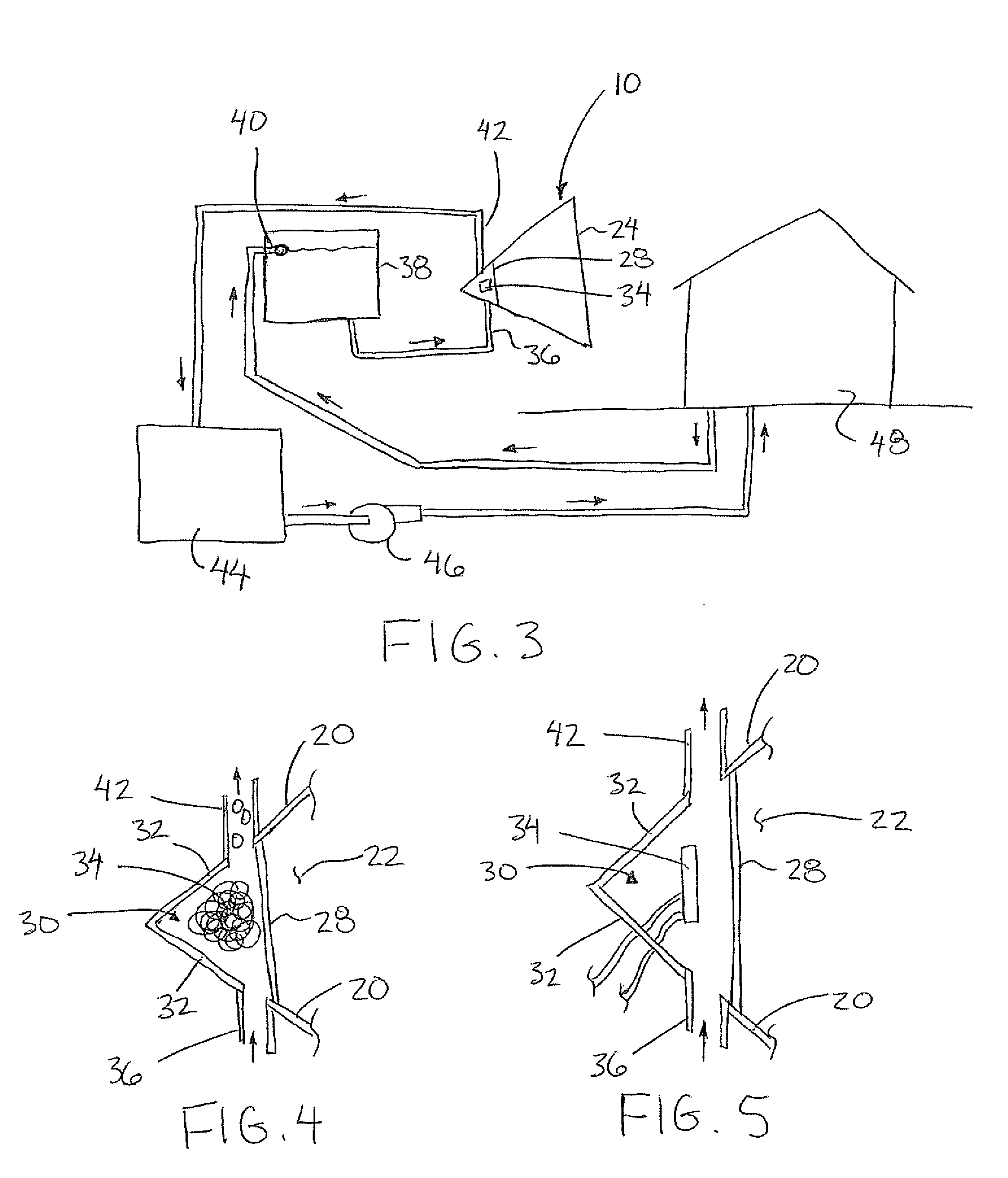
[0012]The solar collector of the present invention provides an improved boiler compared to prior art solar boilers in that the actual boiler chamber locating the heat transfer fluid therein is very small and concentrated at the focal point of a single focussing lens. By separating the target chamber and the focussing lens with an insulated chamber therebetween, heat losses from the boiler are minimized. The minimal size of the target chamber adjacent the focal point of the focussing lens permits very high temperatures to be achieved for optimal efficiency in energy recovery at the outlet of the boiler.
[0031]Alternatively, when the target object comprises a solar cell, the configuration of the target chamber provides efficient cooling to the solar cell with a minimum of losses in conveying the solar rays from the focussing lens to the solar cell due to the insulated chamber spanning the majority of the housing between the focussing lens and the target glass adjacent the focal point of the focussing lens.

Problems solved by technology

Typically in the prior art, the heat transfer fluid is located in a large chamber such that the boiler area is vary large having potential for large convective losses.
Furthermore, the large areas have limited capacity to heat the exchanger fluid to very elevated temperatures due to the potential for convective losses.
No mechanism is provided for cooling the cell however and accordingly the amount of concentration of the solar rays must be limited to prevent overheating.
Even when the cell does not overheat, the lack of any mechanism to capture the heating results in a considerable waste of energy in the form of wasted heat.
The optical concentrators are in direct contact with the chamber locating the heat transfer fluid surrounding the solar cell so that there is still potential for considerable conductive heat losses through the optical concentrator.
Furthermore, the overall combination of lenses is particularly complex so that it would be particularly difficult to vary the scale of the solar collector for different applications.

Method used


Image

  • Solar Heat Collector
  • Solar Heat Collector
  • Solar Heat Collector

Examples


Embodiment Construction

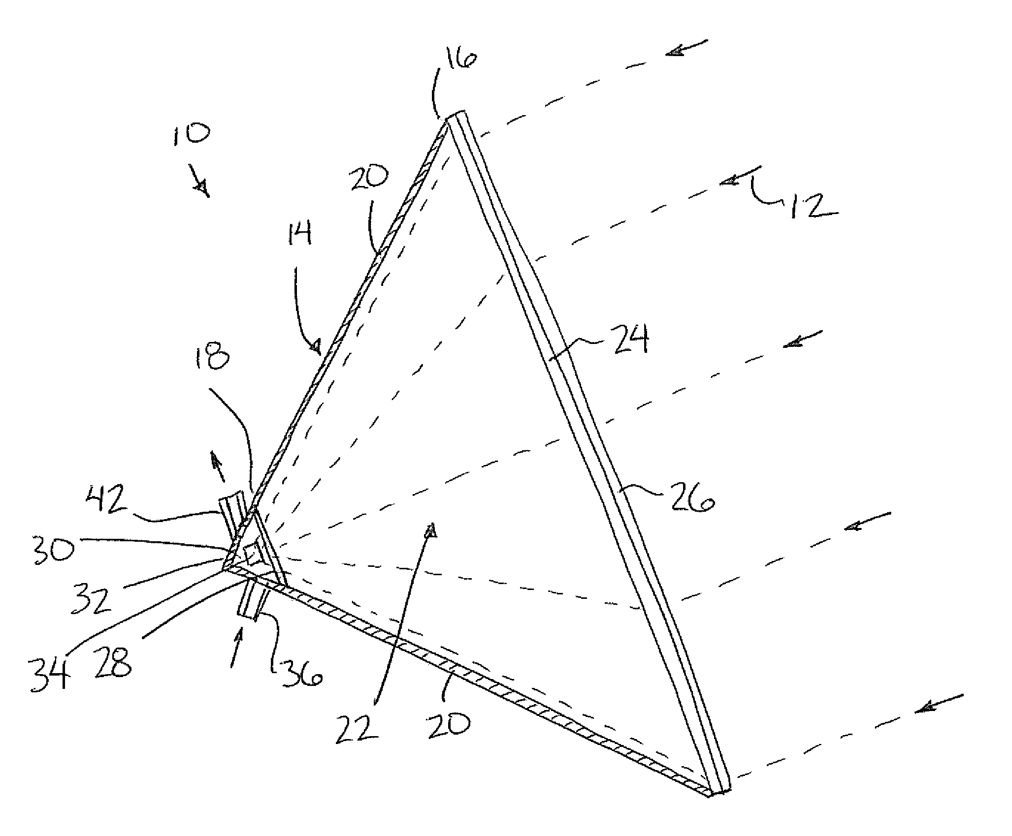
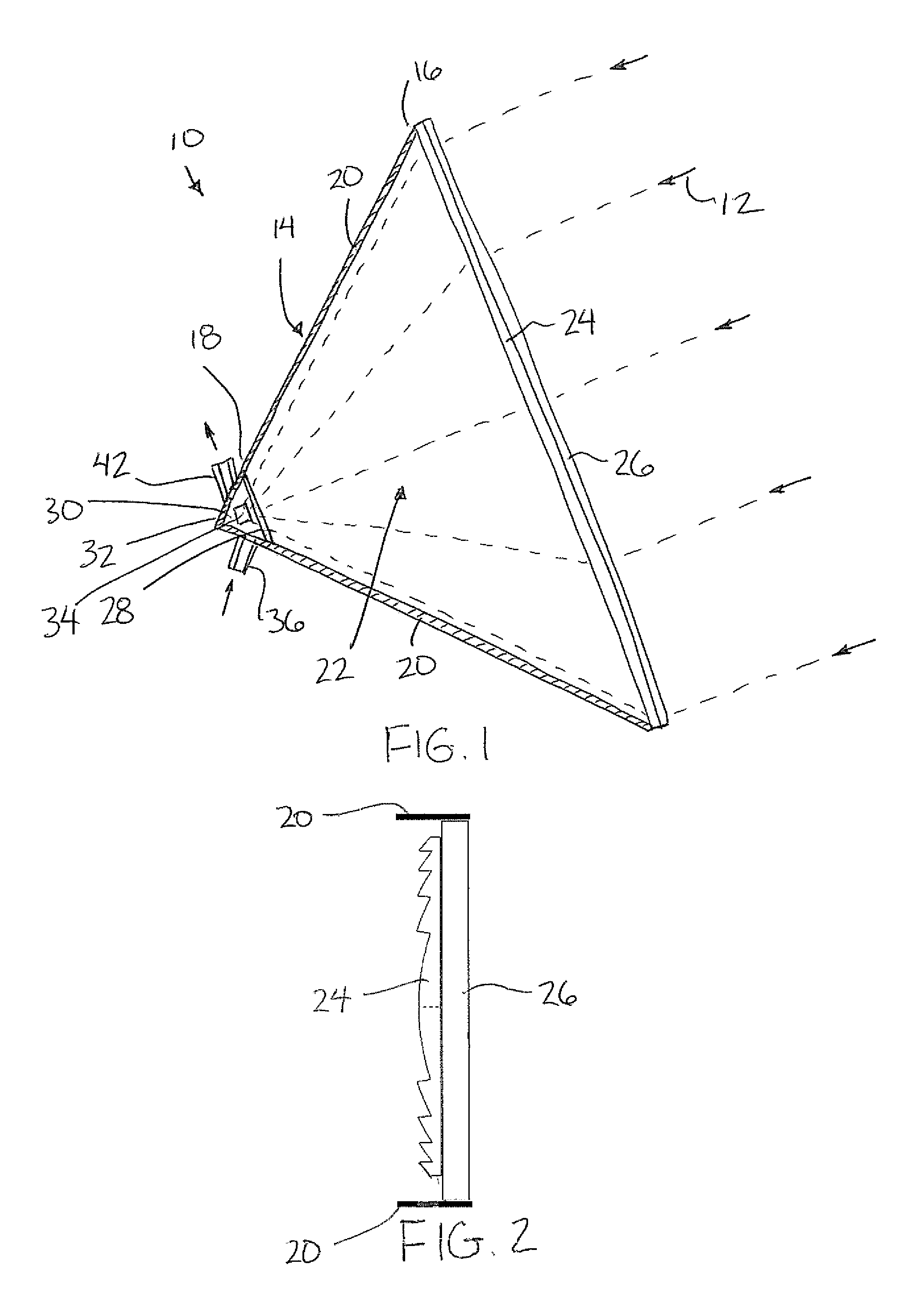
[0058]Referring to the accompanying figures there is illustrated a solar heat collector generally indicated by reference numeral 10. The collector 10 is arranged to collect solar rays 12 from the sun to convert the solar rays into a usable form of energy for performing useful work.

[0059]Although various embodiments are disclosed in the accompanying specification, the common features of the various embodiments will first be described.

[0060]The collector 10 includes a housing 14 extending generally in a longitudinal direction from a receiving end 16 to a target end 18. The housing is arranged to be aligned such that the longitudinal direction is generally aligned with the direction of the solar rays which are received into the receiving end 16 of the housing. The collector serves to direct the rays inwardly towards the target end 18 of the housing.

[0061]The housing includes insulated housing walls 20 which surround an insulated chamber 22 of the housing. The walls surround the chamber...


PUM


Abstract

A solar heat collector includes a housing defining an insulated chamber extending from a focusing lens at a solar receiving end to a target glass at a target end forming a boundary wall between the insulated chamber and a target chamber receiving a heat transfer fluid therein. A target object is supported in the target chamber at the focal point of the focusing lens so as to be surrounded by the heat transfer fluid. In a preferred embodiment a heat engine is supported on the target end of the housing such that the target object and heat transfer fluid are the heat source of the heat engine.

Description

[0001]This application claims the benefit under 35 U.S.C. 119(e) of U.S. provisional application Ser. No. 61 / 364,064, filed Jul. 14, 2010.FIELD OF THE INVENTION[0002]The present invention relates to a solar heat collector including a focusing lens for focusing solar rays from the sun onto a target object surrounded by a heat exchanging fluid.BACKGROUND[0003]It is known to use the rays from the sun to heat a fluid for various uses including the heating of buildings or performing various forms of useful work. Examples of solar boilers are described in U.S. Pat. Nos. 4,057,048 by Maine; 4,246,886 by Sitzlar; 4,056,093 by Barger; and 5,191,875 by Edling et al. Typically in the prior art, the heat transfer fluid is located in a large chamber such that the boiler area is vary large having potential for large convective losses. Furthermore, the large areas have limited capacity to heat the exchanger fluid to very elevated temperatures due to the potential for convective losses.[0004]In oth...

Claims


Application Information

Patent Timeline
IPC IPC(8): F03G6/06F24J2/08F24S23/30
CPCF24J2/085F24J2/542Y02E10/47Y02E10/43Y02E10/46F24S23/31F24S30/452
Inventor LIEVRE, LAURIER
Owner LIEVRE LAURIER
Learn More