

Solar power concentrating system
- Summary
- Abstract
- Description
- Claims
- Application Information
AI Technical Summary
Benefits of technology
Problems solved by technology
Method used
Image

Examples
first embodiment
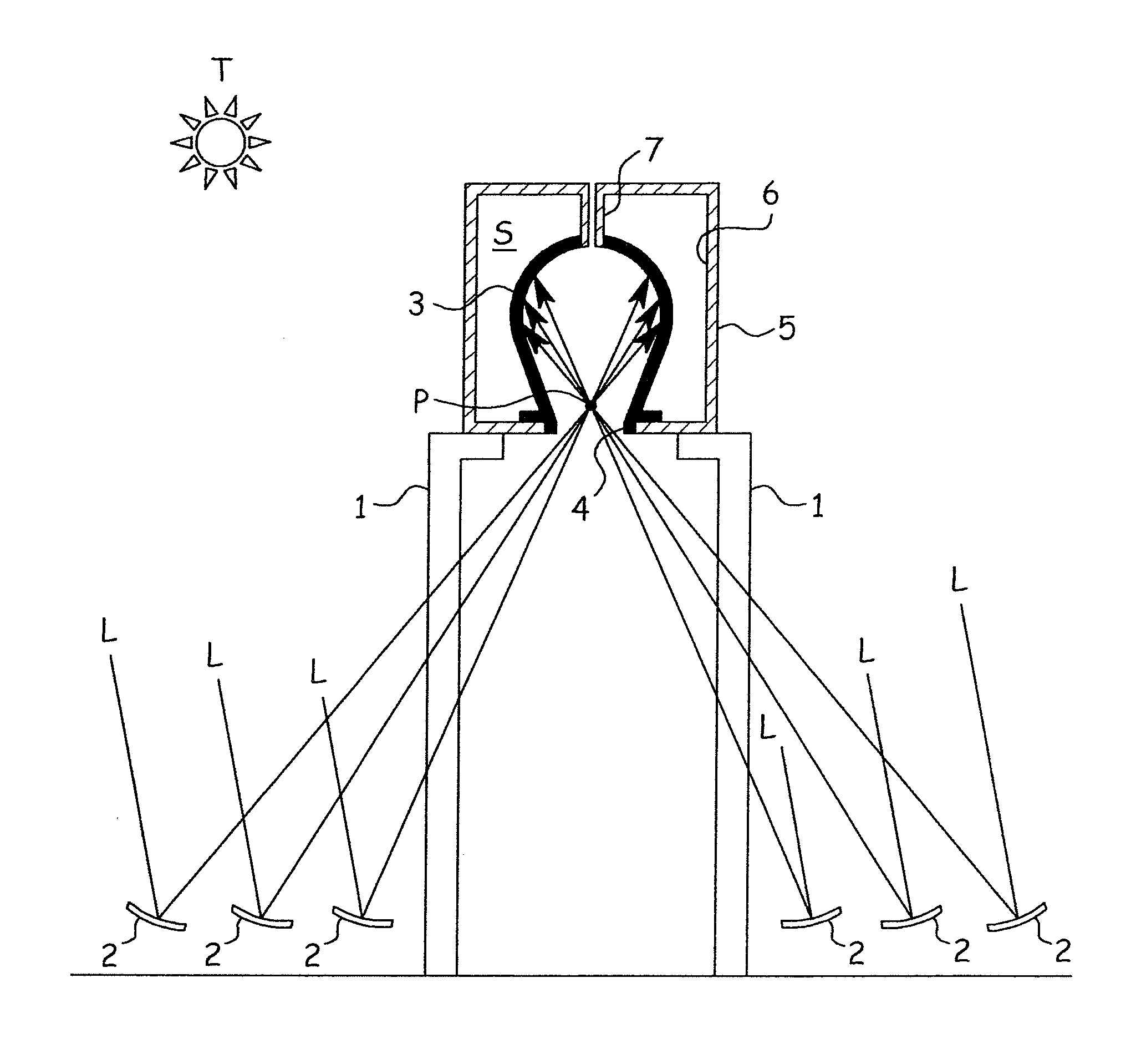
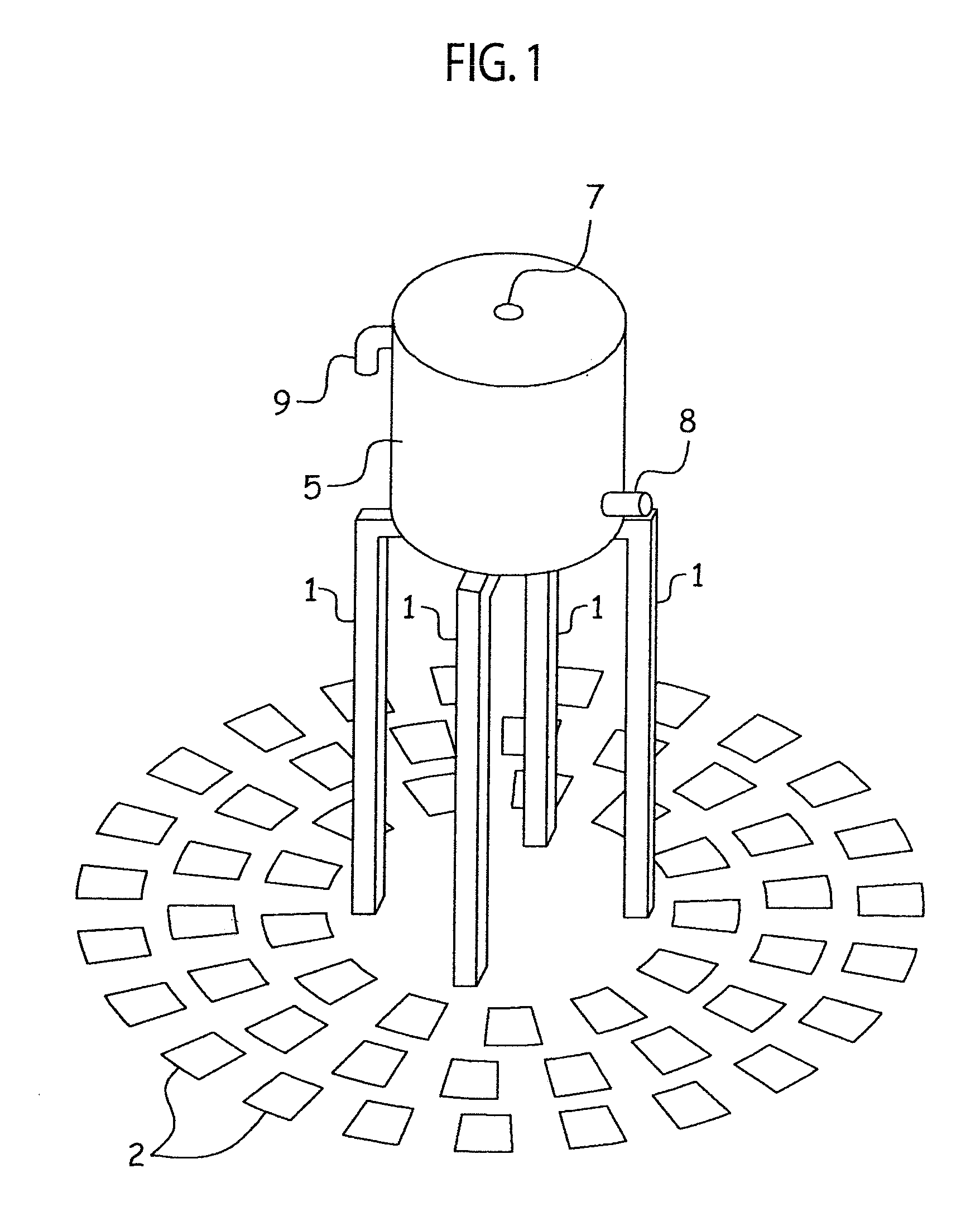
[0011]FIGS. 1 to 3 are views illustrating the first embodiment of the present invention. At the center of a solar concentrating system according to the present embodiment, four supports 1 having a predetermined height (about 10 m) are uprightly arranged. Around the supports 1, there are a plurality of heliostats 2 to follow the sun T and reflect sunlight L toward a single target position P.
[0012]The tops of the four supports 1 support a stationary receiver 3. The receiver 3 has an inverted container shape (inverted pot shape) having an opening 4 at a lower side thereof and a predetermined inner space. The receiver 3 is generally made of black carbon material and an inner face thereof is covered with a silicon carbide (SiC) film. Accordingly, the color of the inner face of the receiver 3 is black to realize a very high absorptance for the sunlight L. Nearly at the center of the opening 4 of the receiver 3, the virtual target P of the heliostats 2 is positioned.
[0013]Formed around the...
second embodiment
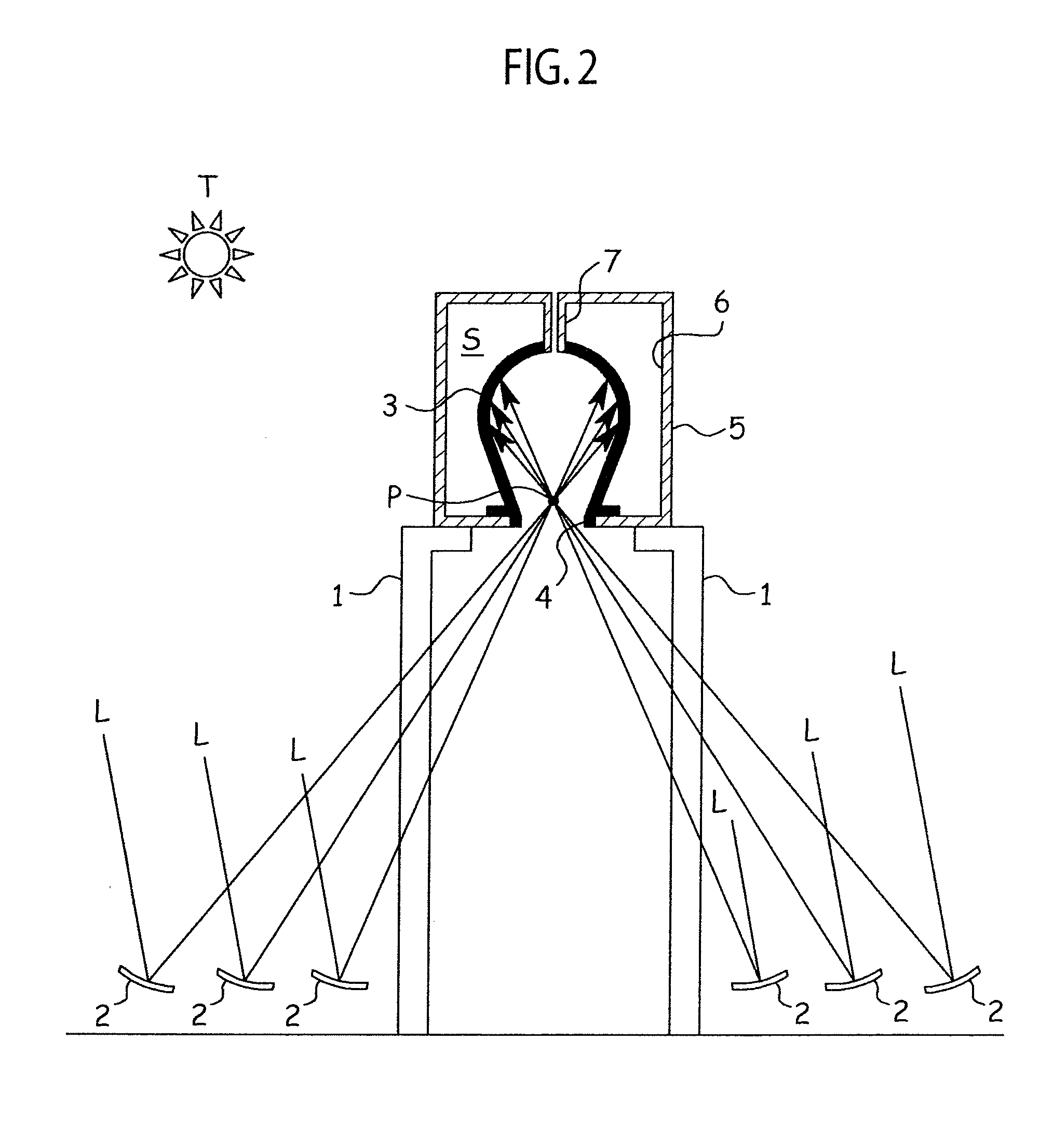
[0025]FIG. 4 is a view illustrating the second embodiment of the present invention. The present embodiment has components that are similar to those of the first embodiment. The similar components are represented with common reference marks to omit a repetition of explanation.
[0026]According to the present embodiment, the shape of a receiver 10 is cylindrical having a top face, like a housing 5. The receiver 10 that is cylindrical and has the top face is easy to form. The diameter of an opening 11 is larger than that of the preceding embodiment, and therefore, components of sunlight L going outside due to reflection may slightly increase. The larger opening 11, however, is capable of receiving sunlight L even if an accuracy of collecting sunlight from heliostats is low. The height of the cylindrical shape of the receiver 10 may be increased to decrease a solid angle from an incident point on an inner face of the receiver 10 to the opening 11, so that sunlight L scattered by the inner...
third embodiment
[0027]FIG. 5 is a view illustrating the third embodiment of the present invention. The present embodiment has components that are similar to those of the above-mentioned embodiments. The similar components are represented with common reference marks to omit a repetition of explanation.
[0028]According to the present embodiment, a receiver 12 is integrally formed with a housing 13. The housing 13 is divided into an upper member 14 and a lower member 15 that are welded together with peripheral flanges 14f and 15f. The receiver 12 has an inverted container shape with a narrow opening 16, like that of the first embodiment. The receiver 12 is integrally and continuously formed from a bottom face of the lower member 15 from the same material. A smoke vent 7 is formed from the upper member 14 and is passed through and welded to an upper part of the receiver 12.
[0029]According to the present embodiment, water W is used as a heating fluid. The water W is supplied into an inlet 8 and is passed...
PUM
 Abstract
Description
Claims
Application Information