Nerve Path Adaptable Nerve Testing Device

a nerve testing and nerve conduction technology, applied in the field of peripheral nerve nerve devices, can solve the problems of inaccurate readings, time-consuming and labor-intensive test marking, etc., and achieve the effect of determining the proper position quickly and easily

Inactive Publication Date: 2012-01-19
ODDERSON IB RASK
View PDF30 Cites 10 Cited by
  • Summary
  • Abstract
  • Description
  • Claims
  • Application Information

AI Technical Summary

Benefits of technology

[0008]It is an object of the present invention to provide a nerve stimulator measuring device that enables a physician to easily and quickly determine the proper position of the nerve stimulator.

Problems solved by technology

The act of measuring and marking several reference points on the forearm and hand is very time consuming.
Also, because the reference points are relatively close, wrong reference points may be used during a test that produces inaccurate readings.

Method used


Image

  • Nerve Path Adaptable Nerve Testing Device
  • Nerve Path Adaptable Nerve Testing Device
  • Nerve Path Adaptable Nerve Testing Device

Examples


first embodiment

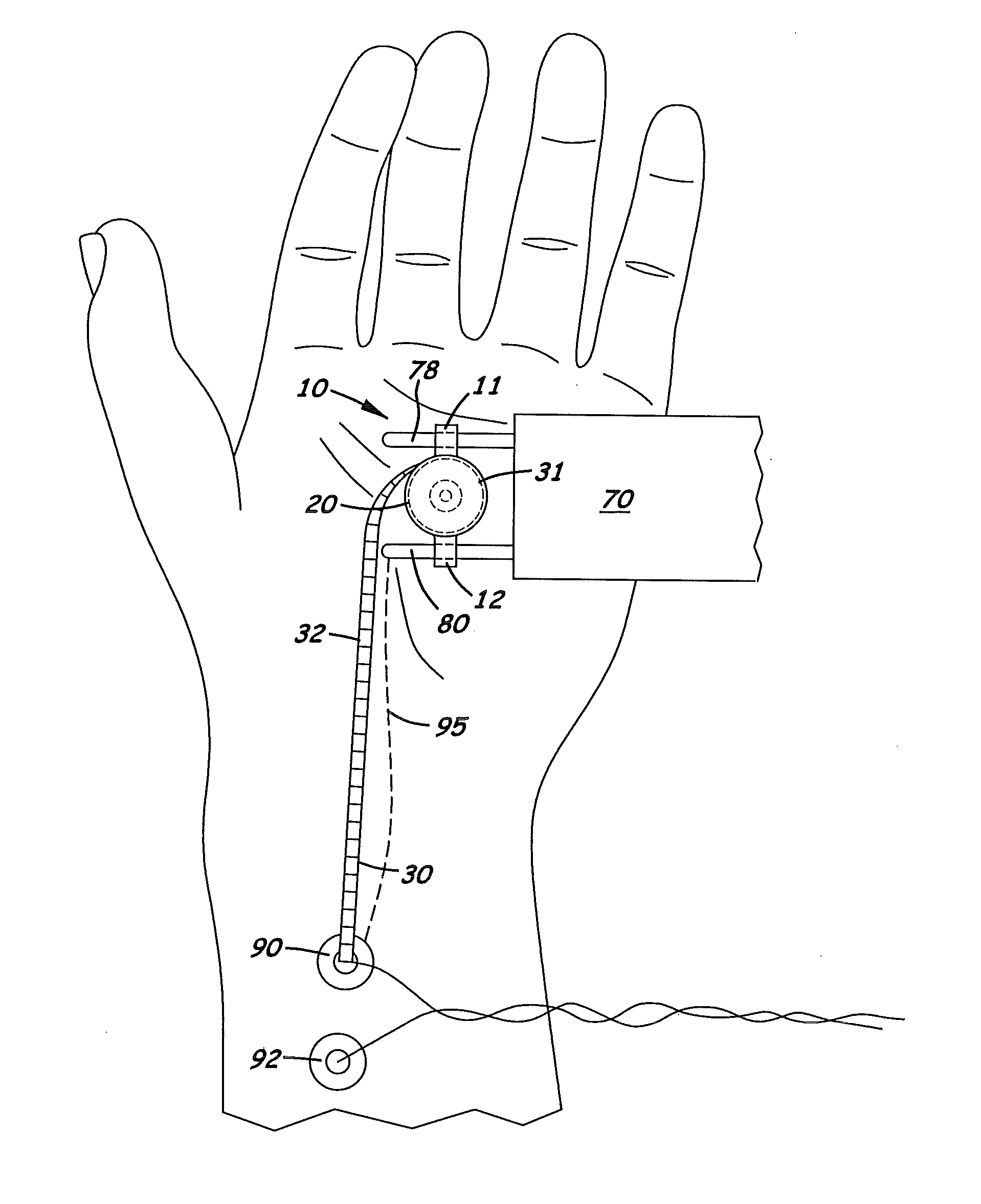
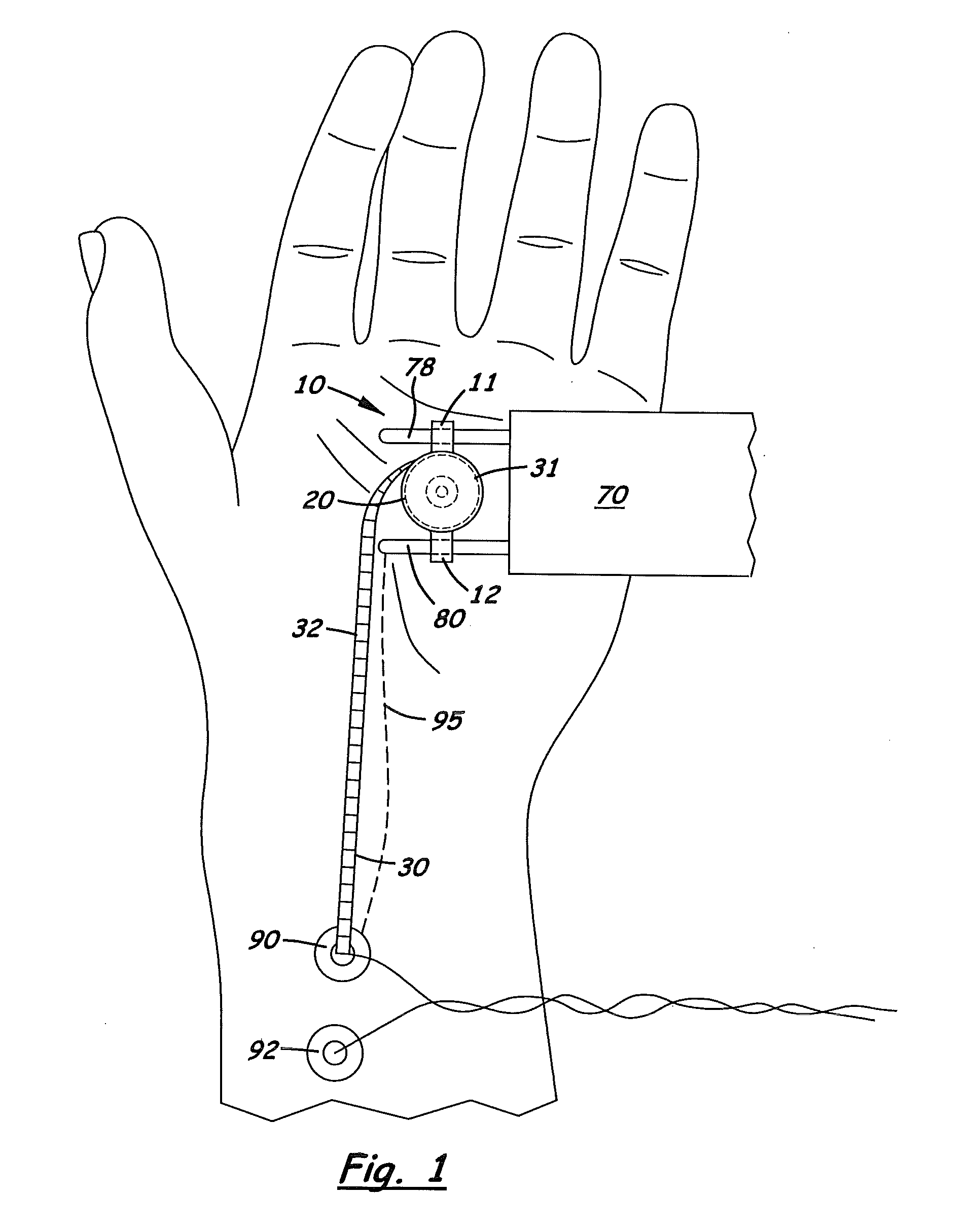
[0051]Shown in the accompanying FIGS. 1-31 are several embodiments of an electrical nerve stimulator measuring device used to measure the distance of conductivity in a peripheral nerve. Referring to the first embodiment shown in FIGS. 1, 3, and 4, the device 10 comprises an outer housing 20 with two side ears 11, 12 that attach to the anode and cathode probes 78, 80, respectively, on a handheld electrical nerve stimulator 70.

[0052]Located inside the outer housing 20 is a retractable spool 31 with a flexible tape 30 with length measure units 32 printed thereon. In the preferred embodiment, the two ears 11, 12 include two bores 24, 26 designed to slidingly receive the anode and cathode probes, 78, 80 respectively. The outer housing 20 is aligned on the probes 78, 80 so that the tape measure 30 unwinds around a center axis that is perpendicular to the longitudinal axis of the two probes 78, 80.

second embodiment

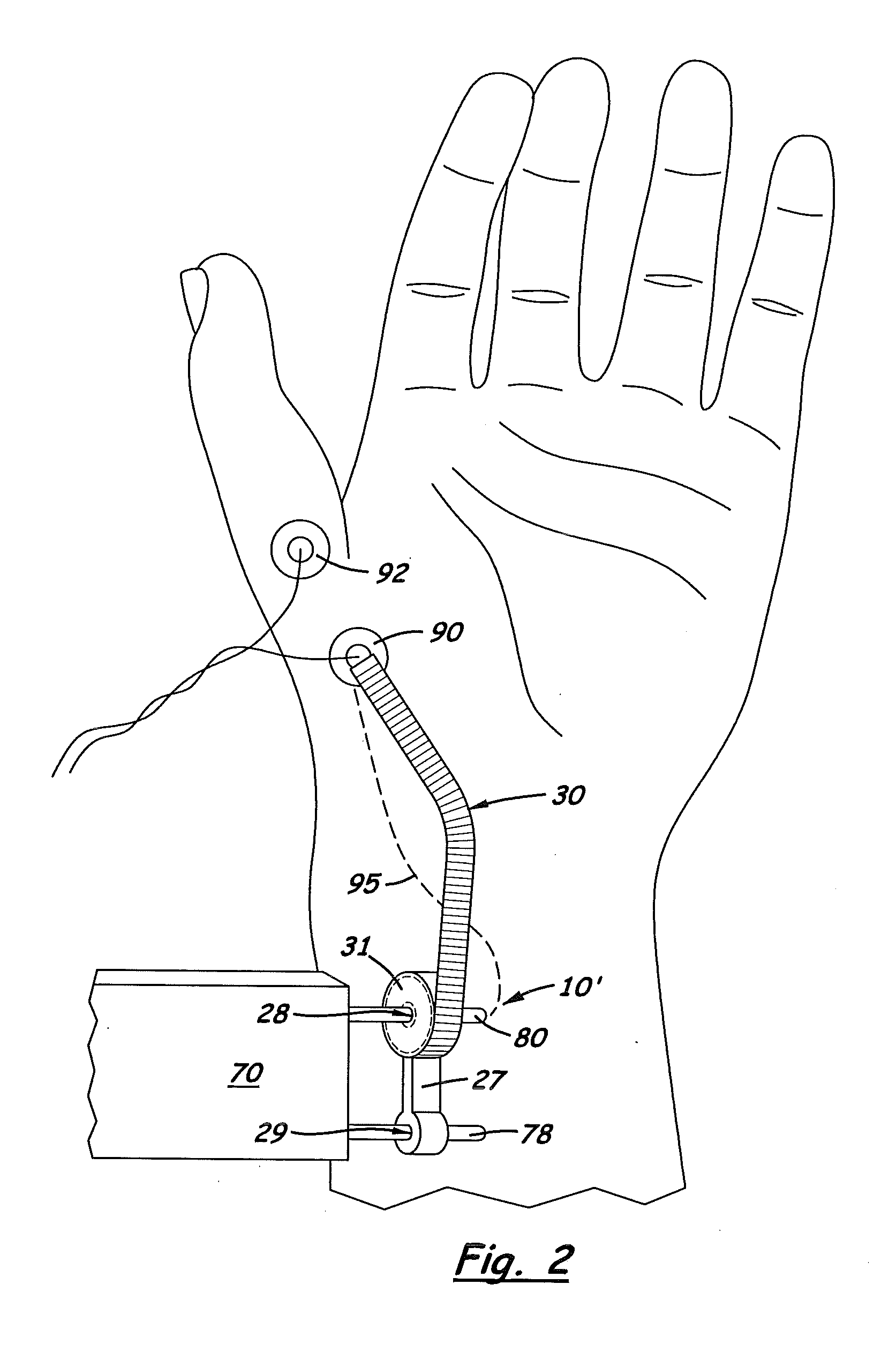
[0053]the device 10′, shown in FIGS. 2, 5 and 6, comprises the tape measure 30 also disposed inside an outer housing 20′ designed to be coaxially aligned around the cathode probe 80. The outer housing 20′ includes a center bore 28 that receives the cathode probe 80 on the electrical nerve stimulator 70. A portion 27 of the outer housing 20′ extends laterally and includes a second bore 29 designed to slidingly receive the anode probe 78. The spool 31 for the tape measure 30 is aligned inside the outer housing 20′ so that it unwinds around a center axis coaxially aligned with the cathode probe 80. When properly assembled on the electrical nerve stimulator 70, the anode probe 78 extends through the second bore 29 and prevents the outer housing 20′ from rotating on the stimulator 70.

third embodiment

[0054]FIGS. 7 and 8 show the measuring device, denoted 10″, design to be used with an electro-magnetic nerve stimulator 85. Device 10″ comprises two clamping members 86, 87 located on the opposite sides of a cylindrical shaped outer housing 20″. Like the first two embodiments, located inside the outer housing 20″ is a retractable spool 31 with a flexible tape measure 30 wound thereon. Formed on the side of the outer housing 20″ is an exit port 88 through which the distal end of the tape measures 30 extends. The two clamping members 86, 87 are designed to extend and adjustably squeeze around the circular body of the electrical nerve stimulator 85. A threaded bolt 100 and nut 99 are used to apply a clamping force to the two clamping members 86, 87. The outer housing 20 is aligned on the two clamping members 86, 87 to that its center axis is perpendicular to the longitudinal axis on the two clamping members 86, 87. When properly assembled, the exit port 88 is aligned over the center ax...


PUM


Abstract

A visual distance nerve measuring electrode wire used to measure the length of electrical conduction of a nerve. The device includes a single flexible wire surrounded by an outer insulating sheath longitudinally aligned and surrounding the wire. An recording electrode is attached to one end of the wire and a plug connector that attaches to a suitable recording device is attached to opposite end of the wire. Formed on the insulating sheath are a plurality of small visual distance indicators formed on the wire at known distances and integrals. During use, the physician is able to accurate map the path of a nerve and determine the conductivity of the nerve at different points.

Description

[0001]This is a continuation-in-part application based on pending U.S. patent application (Ser. No. 12 / 927,508), filed on Jan. 2, 2009, which is a continuation-in-part application of 11 / 021,299, filed Dec. 23, 2004 and now U.S. Pat. No. 7,496,407 which were based on provisional patent applications (Ser. No. 60 / 532,029) filed on Dec. 23, 2003, and (Ser. No. 60 / 541,511) filed on Feb. 3, 2004.BACKGROUND OF THE INVENTION[0002]1. Field of the Invention[0003]This invention relates to devices used to measure nerve conduction in peripheral nerves and more particularly, to such devices that measure the conduction time and amplitude of a test signal applied to a nerve.[0004]2. Description of the Related Art[0005]It is common practice in medicine to measure the electrical conduction on a peripheral nerve. For example, when diagnosing carpel tunnel syndrome it is common for a physician to measure the electrical conduction in the median nerve as it extends from the forearm, through the wrist and...

Claims


Application Information

Patent Timeline
Patent Type & Authority Applications(United States)
IPC IPC(8): A61B5/05A61B5/04A61N1/36G01B3/10
CPCA61B5/0002A61B5/04001A61B5/1072G01B2003/1094A61N1/36003A61N1/36014G01B3/1005A61B5/4893A61B5/4041A61B5/24G01B3/1094
Inventor ODDERSON, IB RASK
Owner ODDERSON IB RASK
Why Eureka
Try Eureka