Eureka AIR delivers breakthrough ideas for toughest innovation challenges, trusted by R&D personnel around the world.

Systems and methods for radial steering of electrode arrays

Active Publication Date: 2012-01-19
BOSTON SCI NEUROMODULATION CORP
View PDF8 Cites 356 Cited by
  • Summary
  • Abstract
  • Description
  • Claims
  • Application Information

AI Technical Summary

Problems solved by technology

This results in the unwanted stimulation of neighboring neural tissue, undesired side effects and an increased duration of time for the proper therapeutic effect to be obtained.

Method used


Image

  • Systems and methods for radial steering of electrode arrays
  • Systems and methods for radial steering of electrode arrays
  • Systems and methods for radial steering of electrode arrays

Examples


Embodiment Construction

[0037]The present invention is directed to the area of devices and methods for brain stimulation including deep brain stimulation. In addition, the invention is directed to devices and method for brain stimulation using a lead having a plurality of segmented electrodes.

[0038]A lead for deep brain stimulation may include stimulation electrodes, recording electrodes, or a combination of both. A practitioner may determine the position of the target neurons using the recording electrode(s) and then position the stimulation electrode(s) accordingly without removal of a recording lead and insertion of a stimulation lead. In some embodiments, the same electrodes can be used for both recording and stimulation. In some embodiments, separate leads can be used; one with recording electrodes which identify target neurons, and a second lead with stimulation electrodes that replaces the first after target neuron identification. A lead may include recording electrodes spaced around the circumferen...


PUM


Abstract

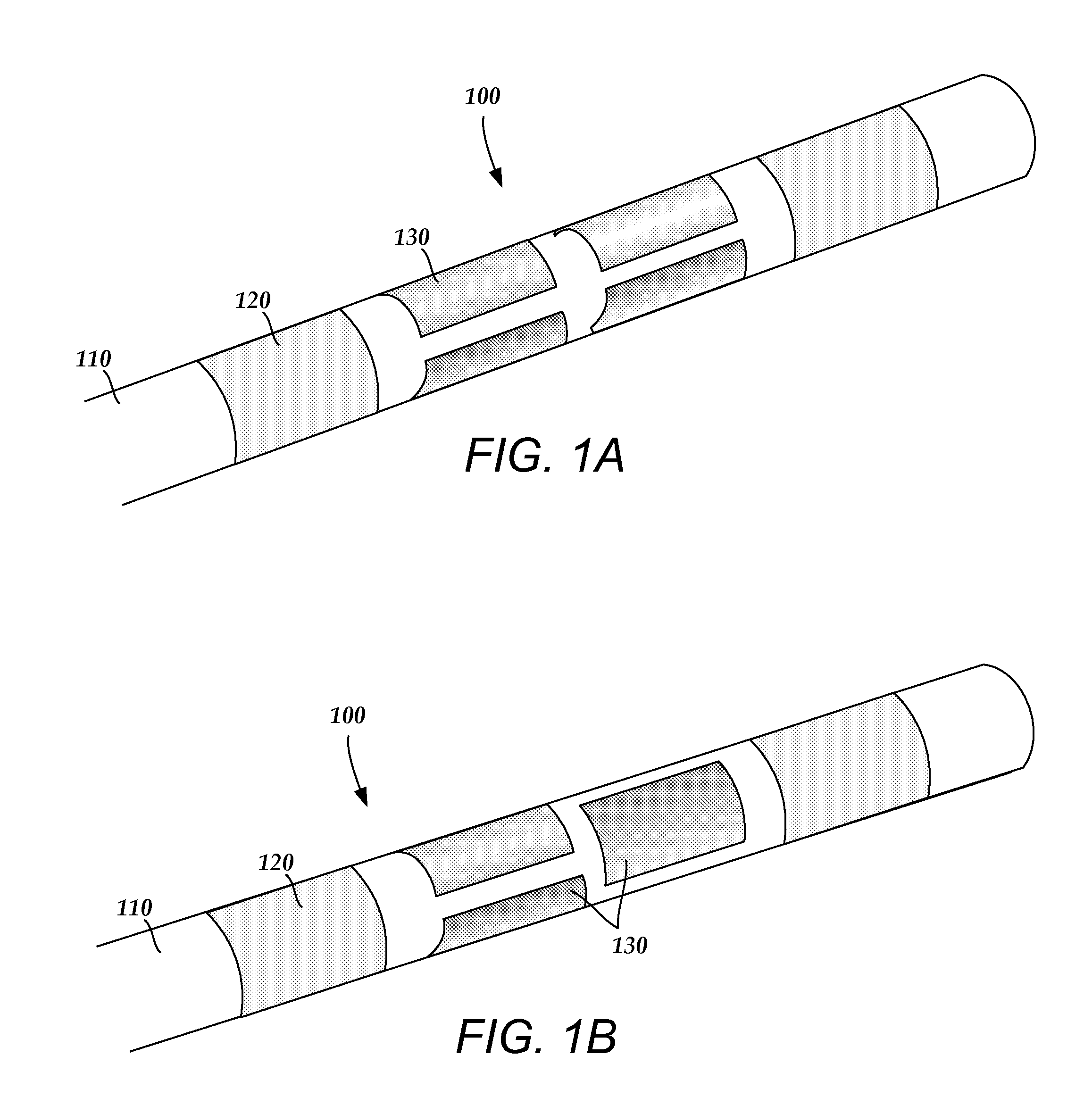
A device for brain stimulation includes a lead having a longitudinal surface, a proximal end and a distal end. A plurality of electrodes are disposed along the longitudinal surface of the lead near the distal end of the lead. At least one marker is disposed on the longitudinal surface of the lead. The at least one marker is configured and arranged to identify a relative position of the plurality of electrodes.

Description

CROSS-REFERENCE TO RELATED APPLICATIONS[0001]This application claims the benefit under 35 U.S.C. §119(e) of U.S. Provisional Patent Application Ser. No. 61 / 364,960 filed on Jul. 16, 2010, which is incorporated herein by reference.FIELD[0002]The invention is directed to devices and methods for brain stimulation including deep brain stimulation. In addition, the invention is directed to devices and method for brain stimulation using a lead having at least one marker to identify the position of the plurality of electrodes.BACKGROUND[0003]Deep brain stimulation can be useful for treating a variety of conditions including, for example, Parkinson's disease, dystonia, essential tremor, chronic pain, Huntington's Disease, levodopa-induced dyskinesias and rigidity, bradykinesia, epilepsy and seizures, eating disorders, and mood disorders. Typically, a lead with a stimulating electrode at or near a tip of the lead provides the stimulation to target neurons in the brain. Magnetic resonance ima...

Claims


Application Information

Patent Timeline
IPC IPC(8): A61N1/05A61B19/00A61N1/36
CPCA61N1/36182A61N1/0534
Inventor PIANCA, ANNE MARGARETMOFFITT, MICHAEL ADAM
Owner BOSTON SCI NEUROMODULATION CORP
Why Eureka
Eureka Blog
Learn More