Organic light emitting diode display and driving method thereof

a light-emitting diode and display device technology, applied in the direction of instruments, computing, electric digital data processing, etc., can solve the problems of low luminous efficiency and brightness, large power consumption, small viewing angle, etc., and achieve the effect of preventing luminance for the display panel

Active Publication Date: 2012-01-26
LG DISPLAY CO LTD
View PDF4 Cites 47 Cited by
  • Summary
  • Abstract
  • Description
  • Claims
  • Application Information

AI Technical Summary

Benefits of technology

[0020]According to another exemplary embodiment, there is provided an OLED display device including a display panel that is provided with a plurality of pixels each including an OLED which emits light in response to pixel data; a data driving circuit that drives data lines of the display panel; a timing controller that supplies black data to the data driving circuit during a predetermined period directly after system power is applied before the pixel data is supplied; a driving voltage supply circuit that supplies driving voltages to the OLEDs in an initial driving process for applying the black data to the pixels; and a luminance compensation circuit including a current sensing circuit that detects a driving current flowing through the OLEDs by the black data at a first non-emission period after at least one frame has elapsed from a time point where the driving voltage is supplied to the OLEDs, wherein the luminance compensation circuit prevents luminance for the display panel from varying due to variations in external environmental conditions.

Problems solved by technology

The PDP has light weight and thin profile, and is advantageous to a large-sized screen because of simple structure and manufacturing process, but is disadvantageous in that luminous efficiency and brightness are low and power consumption is great.
The TFT LCD (Thin Film Transistor LCD) is a widely used flat display device, but is disadvantageous in that a viewing angle is small and a response speed is low.
In the related art, such an over-current may cause damage in the driving circuits and operation errors in the current feedback algorithm during the initial driving.

Method used


Image

  • Organic light emitting diode display and driving method thereof
  • Organic light emitting diode display and driving method thereof
  • Organic light emitting diode display and driving method thereof

Examples


Embodiment Construction

[0030]Hereinafter, exemplary embodiments of this document will be described with reference to FIGS. 3 to 7.

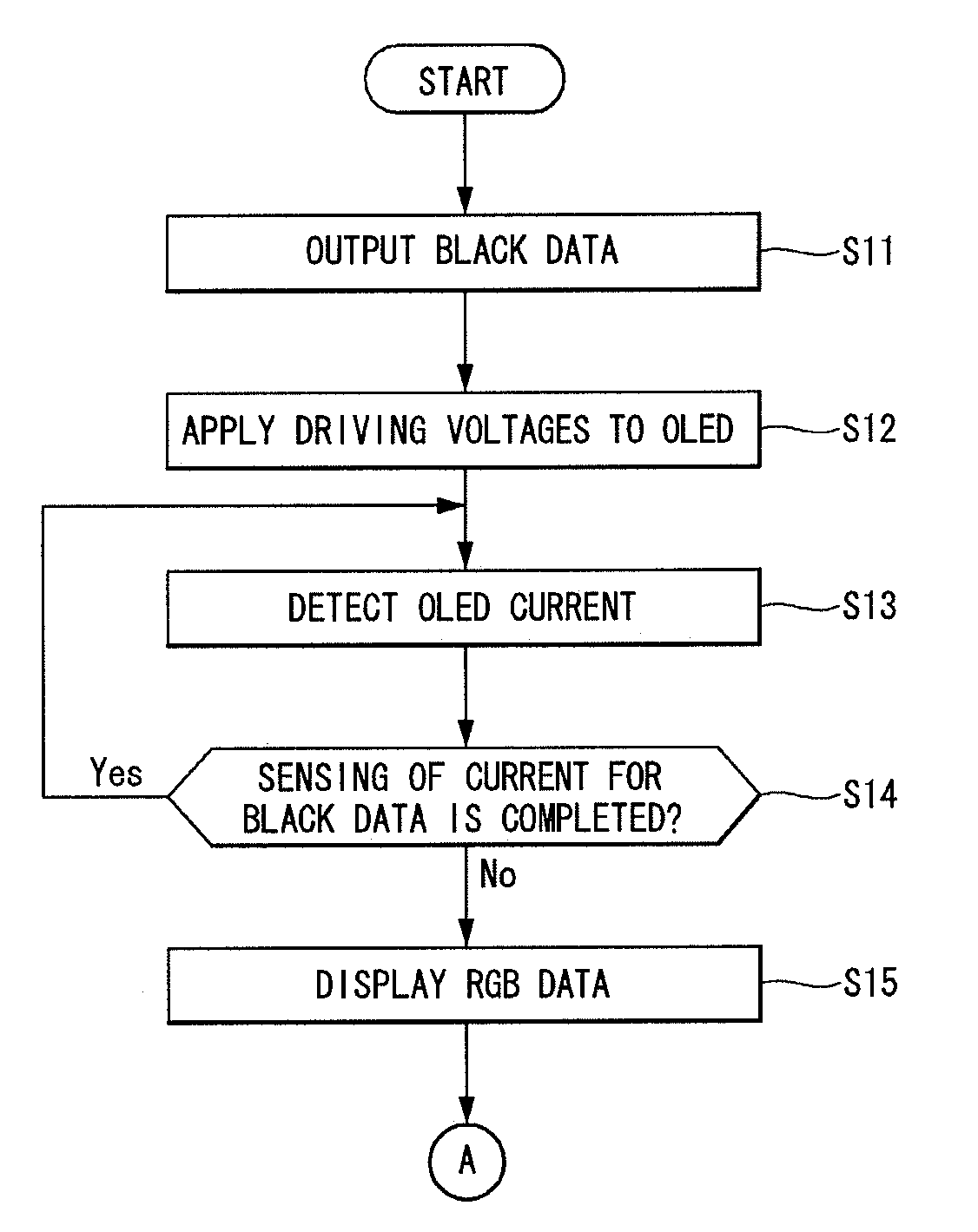
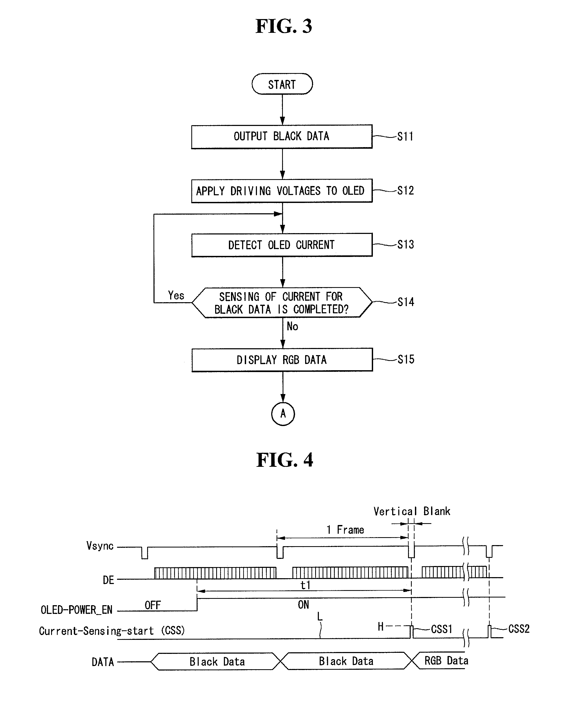
[0031]FIG. 3 shows a driving method of an OLED display device during the initial driving according to an embodiment of this document. FIG. 4 shows application timings of control signals and data during the initial driving and the normal driving. In addition, FIG. 5 shows a driving method of the OLED display device during the normal driving following the initial driving according to an embodiment of this document.

[0032]First, the initial driving according to the embodiment of this document will be described with reference to FIGS. 3 and 4. In the driving method of the OLED display device according to the embodiment of this document, directly after system power is applied to the display device, black data is output referring to a vertical synchronization signal Vsync and a data enable signal DE supplied from an external device (S11). The black data is output during a predetermine...


PUM


Abstract

A driving method of an OLED display device having a plurality of pixels each including an OLED which emits light in response to pixel data, includes applying black data to the pixels during a predetermined period directly after system power is applied, supplying driving voltages to the OLEDs during initial driving where the black data is applied to the pixels, detecting a driving current flowing through the OLEDs by the black data at a first non-emission period after at least one frame has elapsed from a time point where the driving voltages are supplied to the OLEDs, and applying pixel data to the pixels for normal driving subsequent to the initial driving.

Description

[0001]This application claims the benefit of Korean Patent Application No. 10-2010-0070907 filed on Jul. 22, 2010 in Republic of Korea, which is incorporated herein by reference for all purposes as if fully set forth herein.BACKGROUND[0002]1. Field[0003]This document relates to an organic light emitting diode display device and a driving method thereof capable of preventing a luminance variation due to an external temperature or ambient light.[0004]2. Related Art[0005]Flat display devices include liquid crystal displays (“LCDs”), field emission displays (“FEDs”), plasma display panels (“PDPs”), electroluminescence devices, and the like.[0006]The PDP has light weight and thin profile, and is advantageous to a large-sized screen because of simple structure and manufacturing process, but is disadvantageous in that luminous efficiency and brightness are low and power consumption is great. The TFT LCD (Thin Film Transistor LCD) is a widely used flat display device, but is disadvantageous...

Claims


Application Information

Patent Timeline
Patent Type & Authority Applications(United States)
IPC IPC(8): G09G3/30G09G5/10
CPCG09G3/3233G09G2320/0233G09G2320/029G09G2360/16G09G2330/02G09G2330/04G09G2320/0626G09G2330/026
Inventor BYUN, SEUNGCHAN
Owner LG DISPLAY CO LTD
Why Eureka
Try Eureka