Method, apparatus, and system for multi-antenna transmission

a multi-antenna transmission and apparatus technology, applied in the field of communication technologies, can solve the problems that the advantages of mimo and beamforming technology may not be effectively utilized, and achieve the effect of reducing the interference between users, channel capacity in the system and

Inactive Publication Date: 2012-01-26
SNAPTRACK
View PDF12 Cites 5 Cited by
  • Summary
  • Abstract
  • Description
  • Claims
  • Application Information

AI Technical Summary

Benefits of technology

[0020]It can be seen from the preceding technical solutions that embodiments of the present invention implement combined use of both the MIMO and the beamforming technology. The MIMO transmission technology may be used on multiple beamforming arrays, which brings the advantages of the beamforming technology and MIMO into full play. Therefore, the SNR is improved through the array gain of the beamforming to reduce the interference between users, and the channel capacity in the system and the spectrum efficiency are improved through MIMO. Therefore, the technical solution provided in embodiments of the present invention is of practical value.

Problems solved by technology

Therefore, the advantages of MIMO and the beamforming technology may not be utilized effectively.

Method used


Image

  • Method, apparatus, and system for multi-antenna transmission
  • Method, apparatus, and system for multi-antenna transmission
  • Method, apparatus, and system for multi-antenna transmission

Examples


Embodiment Construction

[0032]The technical solution under the present invention is described below with reference to the accompanying drawings. Evidently, the embodiments described below are for the exemplary purpose only, without covering all embodiments of the present invention. Those skilled in the art can derive other embodiments from the embodiments provided herein without making any creative effort, and all such embodiments are covered in the protection scope of the present invention.

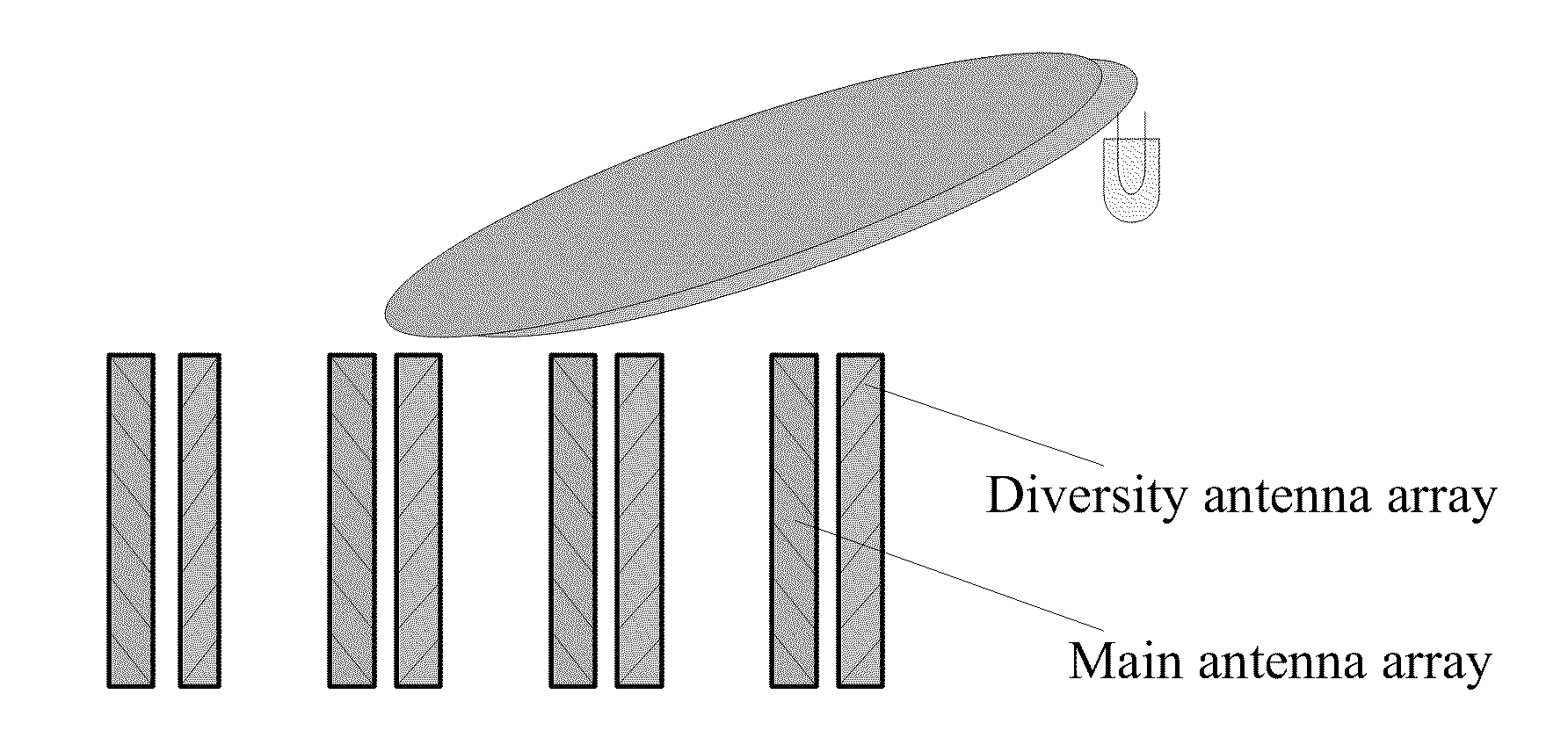
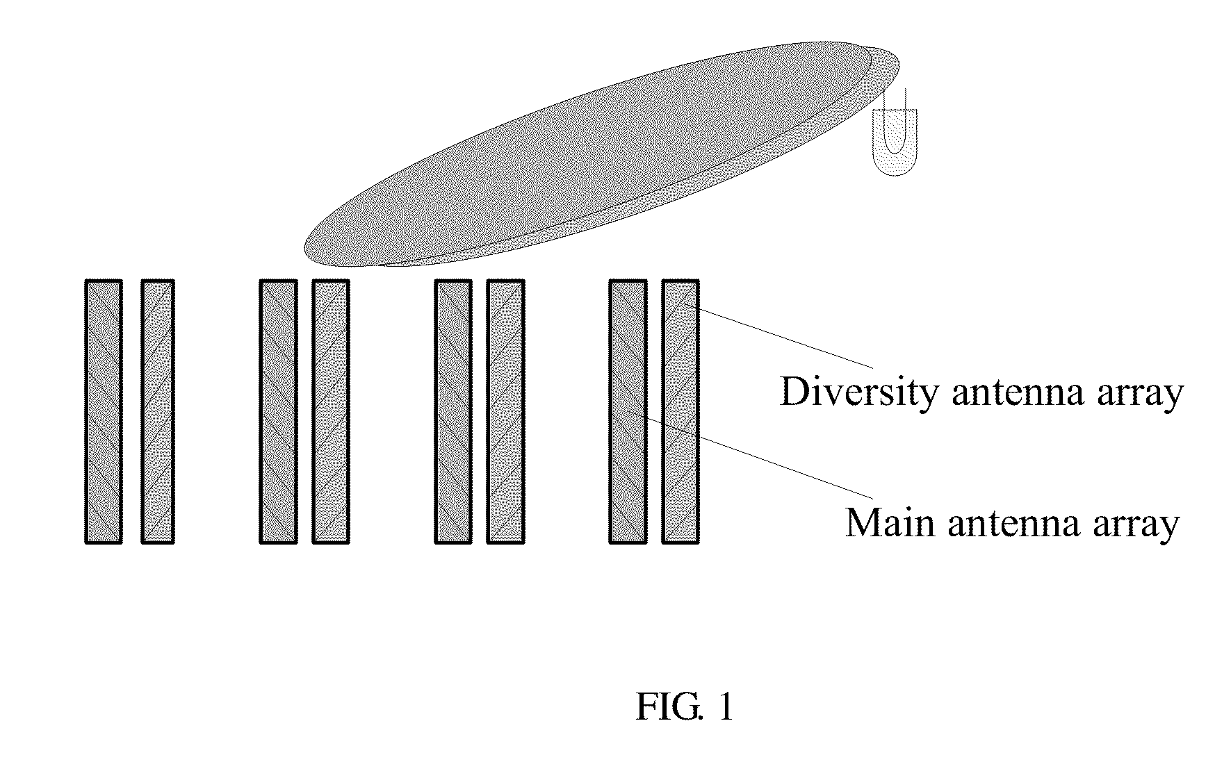
[0033]According to the method for multi-antenna transmission provided in embodiments of the present invention, to achieve the advantages of MIMO and the beamforming technology, these two technologies are combined to be used. That is, the multi-antenna transmission system supports MIMO and the beamforming technology concurrently. For example, a base station supports multiple antenna arrays, each of the antenna arrays uses the beamforming technology, and MIMO is used on the multiple antenna arrays. The MIMO technology inc...


PUM


Abstract

A method for multi-antenna transmission includes allocating a different subcarrier resource or a different code resource to UE-specific reference signals (RSs) corresponding to each beamforming array of multiple beamforming arrays; and using the multiple input multiple output (MIMO) technology on the multiple beamforming arrays. The embodiments of present invention also provide a multi-antenna apparatus and system. Embodiments of the present invention implement combined use of MIMO and the beamforming technology, which brings the advantages of the beamforming technology and MIMO into full play. Therefore, the SNR is improved through the array gain of beamforming arrays to reduce the interference between users, and the channel capacity in the system and the spectrum efficiency are improved through MIMO.

Description

CROSS-REFERENCE TO RELATED APPLICATIONS[0001]This application is a continuation of U.S. patent application Ser. No. 13 / 097675, filed on Apr. 29, 2011, which is a continuation of International Application No. PCT / CN2009 / 074611, filed on Oct. 26, 2009. The International Application claims priority to Chinese patent application No. 200810225165.3, filed on Oct. 29, 2008, all of which are hereby incorporated by reference in their entireties.FIELD OF THE INVENTION[0002]The present invention relates to communications technologies, and in particular, to a method, apparatus, and system for multi-antenna transmission.BACKGROUND OF THE INVENTION[0003]Long term evolution (LTE) in the 3rd Generation Partnership Project (3GPP) is the evolution of the 3G network. The LTE improves the air access technology of the 3G network, adopts orthogonal frequency division multiplexing (OFDM) and multiple input multiple output (MIMO) as the core air interface technology of the radio network evolution, provide...

Claims


Application Information

Patent Timeline
Patent Type & Authority Applications(United States)
IPC IPC(8): H04W72/04
CPCH04B7/0413H04L5/0023H04L5/0026H04L5/0051H04L2025/03426H04L25/0226H04L25/03343H04L27/2613H04L2025/03414H04L25/0204H04B7/0617H04L1/0071
Inventor YU, GANGLOU, YUANZHI
Owner SNAPTRACK
Why Eureka
Try Eureka