
System and method for digital subscriber loop crosstalk cancellation

a technology of digital subscriber loop and crosstalk, applied in the field of system and method for digital subscriber loop crosstalk cancellation, can solve the problems of significant spectral interference between dsl services deployed on different twisted copper pairs in the same cable, and inability to provide high data speeds to customers located more than a few kilometers from the central office. to achieve the effect of reducing crosstalk

Inactive Publication Date: 2012-01-26
ACTELIS NETWORKS INC
View PDF2 Cites 22 Cited by
  • Summary
  • Abstract
  • Description
  • Claims
  • Application Information

AI Technical Summary

Benefits of technology

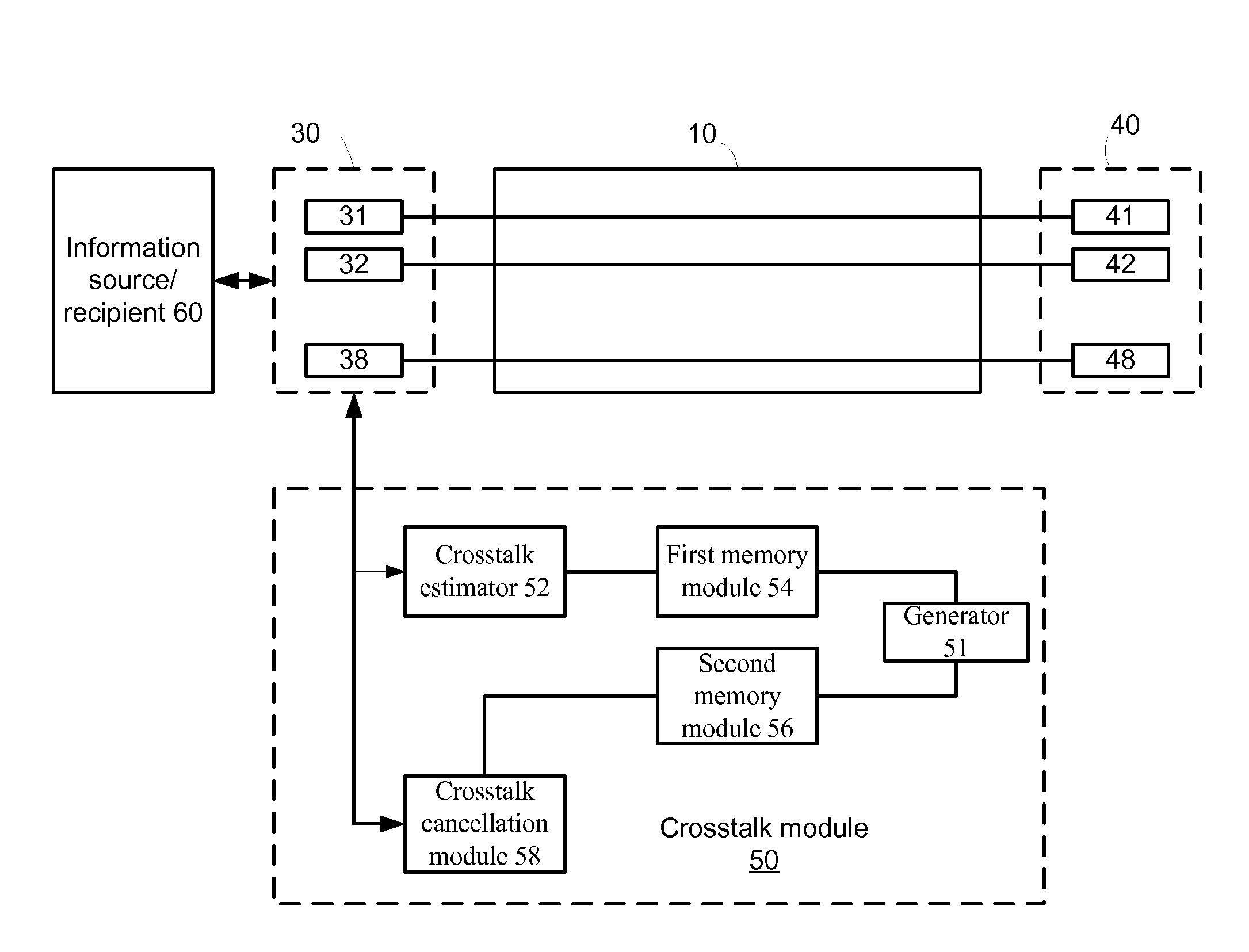
[0015]According to an embodiment of the invention a method for crosstalk cancellation is provided. The method includes: (i) generating estimated crosstalk cancellation matrices for each frequency bin of a group of adjacent frequency bins, wherein each estimated crosstalk cancellation matrix provides an estimation of a crosstalk cancellation that is expected to mitigate crosstalk that is generated at a single frequency bin by an array of transmitters that transmit information over different copper pairs that form a bonded digital subscriber line link; (ii) generating a group crosstalk cancellation matrix based on the estimated crosstalk cancellation matrices, wherein a size of the group crosstalk cancellation matrix is smaller that an aggregate size of the estimated crosstalk cancellation matrices; and (iii) cancelling crosstalk for each frequency bin of the group by utilizing the group crosstalk cancellation matrix.

Problems solved by technology

However, one of the main limitations of DSL technology is that the data capacity of copper wires decreases significantly as the length of the copper loop increases.
Therefore, customers located more than a few kilometers from the Central Office can not be provided with high data speeds over copper wires.
Another significant limitation of DSL technology is the significant spectral interference between DSL services deployed on different twisted copper pairs in the same cable.
Spectral interference between different high-bitrate services in a copper cable is caused by the fact that each copper pair acts as an antenna.
However, since VDSL is typically deployed on short loops, Self-FEXT is a significant concern.
Working on each bin separately requires storing pre-coding / decoding for each bin in a memory which might raise a problem.
A more severe problem might rise from the need to read those matrices in a very high rate.

Method used


Image

  • System and method for digital subscriber loop crosstalk cancellation
  • System and method for digital subscriber loop crosstalk cancellation
  • System and method for digital subscriber loop crosstalk cancellation

Examples


first embodiment

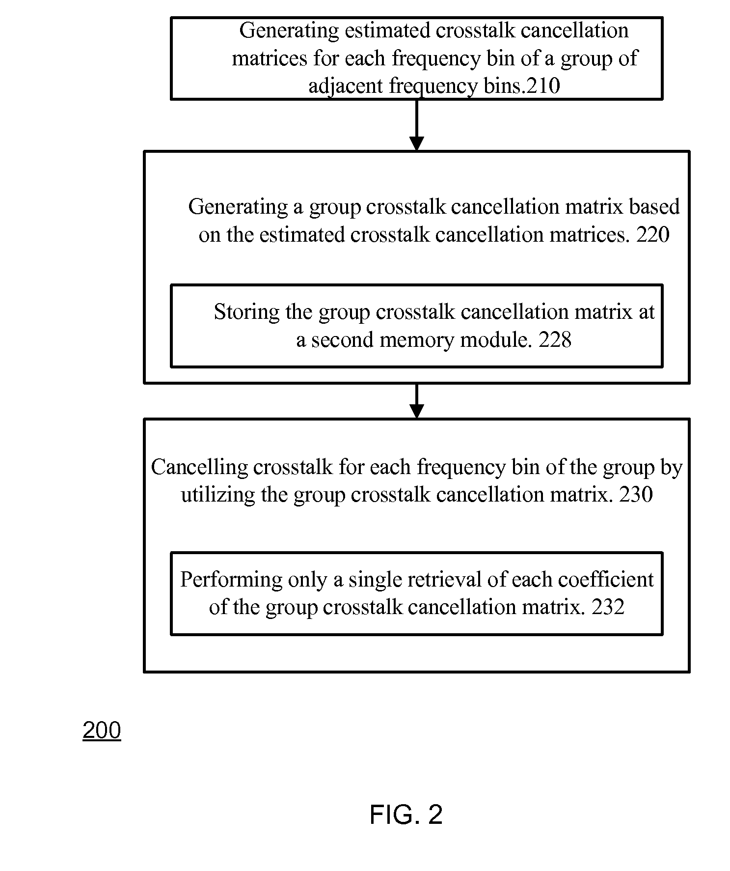
[0068]FIG. 2 illustrates method 200 for crosstalk cancellation, according to an embodiment of the invention.

[0069]Method 200 starts by stage 210 of generating estimated crosstalk cancellation matrices for each frequency bin of a group of adjacent frequency bins.

[0070]Each estimated crosstalk cancellation matrix provides an estimation of a crosstalk cancellation that is expected to mitigate crosstalk that is generated at a single frequency bin by an array of transmitters that transmit information over different copper pairs that form a bonded digital subscriber line link.

[0071]A k′th estimated crosstalk cancellation matrix can provide an estimation of the crosstalk generated at the k′th frequency bin.

[0072]Stage 210 is followed by stage 220 of generating a group crosstalk cancellation matrix based on the estimated crosstalk cancellation matrices.

[0073]The size of the group crosstalk cancellation matrix is smaller that an aggregate size of the estimated crosstalk cancellation matrices...

second embodiment

[0098]According to the second embodiment only one set of coefficients is used for the estimation and for the pre-coding / decoding operations. A reduced set of coefficients is estimated and stored for each group of bins.

[0099]The estimation of the pre-coding / decoding coefficients is performed only for one bin in each group of n bins, and the resulting coefficients are used for the pre-coding / decoding operations on all the bins in the group.

[0100]Therefore, only one memory module may be used for both estimation and pre-coding / decoding. FIG. 4 illustrates a method 400 for crosstalk cancellation, according to an embodiment of the invention.

[0101]Method 400 starts by stage 410 of generating an estimated crosstalk cancellation matrix for a single frequency bin out of a group of adjacent frequency bins. The estimated crosstalk cancellation matrix provides an estimation of a crosstalk cancellation that is expected to mitigate crosstalk that is generated at the single frequency bin by an arra...

third embodiment

[0119]In this embodiment only one set of coefficients is used for the estimation and for the pre-coding / decoding operations itself. As in the previous embodiment, only one reduced set of coefficients is estimated and stored for each group of bins.

[0120]Estimation and adaptation of the pre-coding / decoding coefficients is performed only for one bin in each group of n bins.

[0121]The resulting coefficients are then used for pre-coding / decoding of that one bin in each group, while for the other bins in the group the coefficients are computed in real time using interpolation between the computed coefficients of their group and neighboring groups of bins.

[0122]FIG. 6 illustrates method 600 for crosstalk cancellation, according to an embodiment of the invention.

[0123]Method 600 starts by stage 610 of generating a first estimated crosstalk cancellation matrix for a first frequency bin of a first group of adjacent frequency bins. The first estimated crosstalk cancellation matrix provides an e...


PUM


Abstract

A system and a method for crosstalk cancellation, the method includes: (i) generating estimated crosstalk cancellation matrices for each frequency bin of a group of adjacent frequency bins, wherein each estimated crosstalk cancellation matrix provides an estimation of a crosstalk cancellation that is expected to mitigate crosstalk that is generated at a single frequency bin by an array of transmitters that transmit information over different copper pairs that form a bonded digital subscriber line link; (ii) generating a group crosstalk cancellation matrix based on the estimated crosstalk cancellation matrices, wherein a size of the group crosstalk cancellation matrix is smaller that an aggregate size of the estimated crosstalk cancellation matrices; and (iii) cancelling crosstalk for each frequency bin of the group by utilizing the group crosstalk cancellation matrix.

Description

CROSS REFERENCE TO RELATED APPLICATIONS[0001]This application claims the benefit of U.S. Ser. No. 61 / 140,164, filed on Dec. 23, 2008 and entitled “Memory Optimization for DSL Crosstalk Cancellation Systems”, which is incorporated in its entirety herein by reference.BACKGROUND OF THE INVENTION[0002]One of the most effective and efficient methods of deploying high-speed digital services to business and residential customers is to use one of the many forms of DSL (Digital Subscriber Loop) technologies over copper telephone wires. This approach has become very popular in the last 20 years due to the fact that copper wires are already deployed almost everywhere and are quite easy to access, both at the Central Office (CO) and at the Remote Terminal (RT) or the customer.[0003]However, one of the main limitations of DSL technology is that the data capacity of copper wires decreases significantly as the length of the copper loop increases. Therefore, customers located more than a few kilome...

Claims


Application Information

Patent Timeline
Patent Type & Authority Applications(United States)
IPC IPC(8): H04B1/38
CPCH04B3/32H04L5/14H04L25/0242H04L25/03159H04M11/062H04M3/304H04M3/306H04M3/34H04L25/03343
Inventor DOMANOVITZ, ELADTSUR, EITAN
Owner ACTELIS NETWORKS INC
Learn More