Wavelength selective light cross connect device

a cross-connecting device and selective light technology, applied in the field of wavelength-division multiplex system, electromagnetic transmission, multi-component communication, etc., can solve the problem that switches are essentially vulnerable to external perturbations, and achieve the effect of improving reliability and small mounting area

Inactive Publication Date: 2012-01-26
SANTEC
View PDF1 Cites 21 Cited by
  • Summary
  • Abstract
  • Description
  • Claims
  • Application Information

AI Technical Summary

Benefits of technology

[0022]As described above in detail, according to the present invention, since the wavelength cross connect device is configured as a unit and a plurality of wavelength selective switches are not used, the switch becomes compact, resulting in a small mounting area and reliability is improved. Further, it is possible to provide a multiple input / output wavelength selective cross connect device that is hard to be affected by external perturbations such as vibrations and shocks without using the movable parts such as MEMS.

Problems solved by technology

Further, there is a disadvantage that the switches are essentially vulnerable to external perturbations such as vibrations and shocks since a mirror such as MEMS is mechanically driven.

Method used


Image

  • Wavelength selective light cross connect device
  • Wavelength selective light cross connect device
  • Wavelength selective light cross connect device

Examples


first embodiment

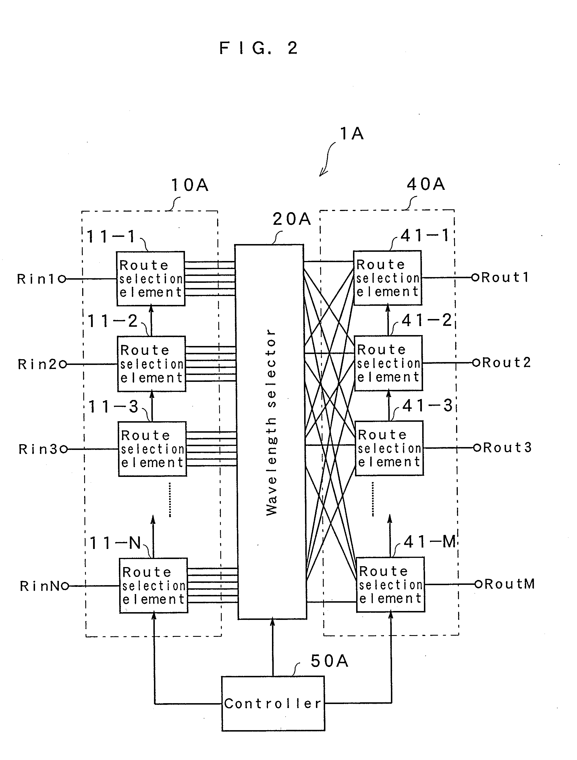
[0045]FIG. 2 is a diagram showing a configuration of a wavelength selective light cross connect device 1A according to a basic configuration of the present invention.

[0046]This cross connect device 1A has N (N is a natural number of 2 or more) input routes Rin1 to RinN and M (M is a natural number of 2 or more) output routes Rout1 to RoutM. The cross connect device 1A is configured of a route selector 10A, wavelength selector 20A, route selector 40A and controller 50A. Here, it is assumed that an optical signal of a first channel inputted to the input route Rin1 is a wavelength division multiplexing optical signal (hereinafter referred to as WDM signal) obtained by multiplexing optical signals of wavelengths λ11 to λL1 (L is a natural number of 2 or more). It is assumed that an optical signal of a second channel inputted to the input route Rin2 is also a WDM signal obtained by multiplexing optical signals of wavelengths λ12 to λL2. Generally describing, it is assumed that a WDM sign...

second embodiment

[0052]Next, more detailed embodiment of the present invention will be described. FIG. 3 is a diagram showing a configuration of a wavelength selective light cross connect device 1B in accordance with a second embodiment of the present invention. The cross connect device 1B in accordance with this embodiment is configured of a route selector 10B, wavelength selector 20B, route selector 40B and controller 50B. A first group of N route selection elements in the route selector 10B is formed of N splitters 12-1 to 12-N that each branch an input into the number of output routes. The splitter 12-1 branches a WDM signal of a first channel inputted from the input route Rin1 into M outputs and outputs each output to the wavelength selector 20B. Similarly, the splitter 12-2 branches a WDM signal of a second channel inputted from the input route Ring into M outputs, and outputs each output to the wavelength selector 20B. The same applies to the other splitters 12-3 to 12-N. Whereby, M WDM signa...

third embodiment

[0073]Next, a third embodiment of the present invention will be described. FIG. 9 is a diagram showing a configuration of a wavelength selective light cross connect device 1C in accordance with the third embodiment of the present invention. In this embodiment, a plurality of route selection elements in a route selector 100 each are formed of an optical switch. That is, the route selector 100 uses N (1×M) optical switches (OSW) 13-1 to 13-N as the route selection elements in place of splitters. The optical switch 13-1 selects a WDM optical signal of a first channel and outputs the selected signal from any of M output terminals to the wavelength selector 20B. The optical switch 13-2 selects a WDM optical signal of a second channel and outputs the selected signal from any of M output terminals to the wavelength selector 20B. The same applies to the other optical switches 13-3 to 13-N. The other configuration is almost the same as that in the second embodiment, and outputs of the optica...


PUM


Abstract

A wavelength selective light cross connect device 1A is configured of a route selector 10A including route selection elements 11-1 to 11-N, wavelength selector 20A, route selector 40A including route selection elements 41-1 to 41-M and controller 50A. The route selection elements 11-1 to 11-N select routes for WDM signals of N channels inputted to input routes Rin1 to RinN, and directs the WDM signals to the wavelength selector 20A. The wavelength selector 20A performs a selection operation to (N×M) WDM signals according to their wavelength, and outputs the signals. Wavelength selection elements 40-1 to 40-M receives different outputs obtained from the respective route selection elements via the wavelength selector 20A, selects routes and outputs the signals from output routes Rout1 to RoutM.

Description

BACKGROUND OF THE INVENTION[0001]1. Field of the Invention[0002]The present invention relates to a wavelength selective light cross connect device having a plurality of input and output routes provided at an optical node corresponding to a branch point in an optical network in an optical telecommunications field.[0003]2. Discussion of the Related Art[0004]A wavelength division multiplexing optical communication technique is applied to a high-speed and large-capacity optical network that supports today's advanced information-telecommunication society. A ROADM (Reconfigurable Optical Add Drop Multiplexer) device having a reconfigurable add-drop function has been introduced to the optical node corresponding to the branch point in the optical network. To realize the ROADM device, a wavelength selective switch (also referred to as WSS) for switching a desired wavelength to a desired direction has received attention. At present, the wavelength selective switch having the number of input r...

Claims


Application Information

Patent Timeline
Patent Type & Authority Applications(United States)
IPC IPC(8): H04J14/00H04B10/27H04B10/291H04J14/02H04Q3/52
CPCH04J14/0212H04J14/022H04Q11/0005H04Q2011/0052H04Q2011/0015H04Q2011/003H04Q2011/0039H04Q2011/0009
Inventor SAKURAI, YASUKIMIYAKOSHI, TAIHEI
Owner SANTEC
Why Eureka
Try Eureka