Board-to-Board Connector

a board-to-board connector and connector technology, applied in the direction of connection contact member materials, fixed connections, coupling devices, etc., can solve the problems that conventional board-to-board connectors cannot meet these requirements, the size and mounting area of board-to-board connectors are difficult to reduce, and the size and mounting area of board-to-board connectors are difficult to meet. these requirements, so as to facilitate manufacture and mounting to the board, the effect of reducing the mounting area

Inactive Publication Date: 2008-10-23
MOLEX INC
View PDF19 Cites 6 Cited by
  • Summary
  • Abstract
  • Description
  • Claims
  • Application Information

AI Technical Summary

Benefits of technology

[0010]The board-to-board connector according to the present invention comprises an integrally formed housing, and a plurality of terminals attached to the housing and forming a plurality of pairs of terminal rows, each terminal having a surface-mount-type solder tail portion, wherein the solder tail portion does not project to the outside of the housing. Therefore, the board-to-board connector according to the present invention can have a large number of terminals and reduce size, reduce the mounting area, facilitate manufacture and mounting to a board, and enhance reliability.

Problems solved by technology

However, the above-mentioned conventional board-to-board connector encounters difficulty in sufficiently reducing the size and mounting area on a circuit board.
In recent years, with advancement of miniaturization and densification of electronic apparatuses, a larger number of electronic components are mounted on a circuit board, so that area for mounting a connector is limited.
However, the conventional board-to-board connector cannot sufficiently meet these requirements.

Method used


Image

  • Board-to-Board Connector
  • Board-to-Board Connector
  • Board-to-Board Connector

Examples


Embodiment Construction

[0027]An embodiment of the present invention will next be described in detail with reference to the drawings.

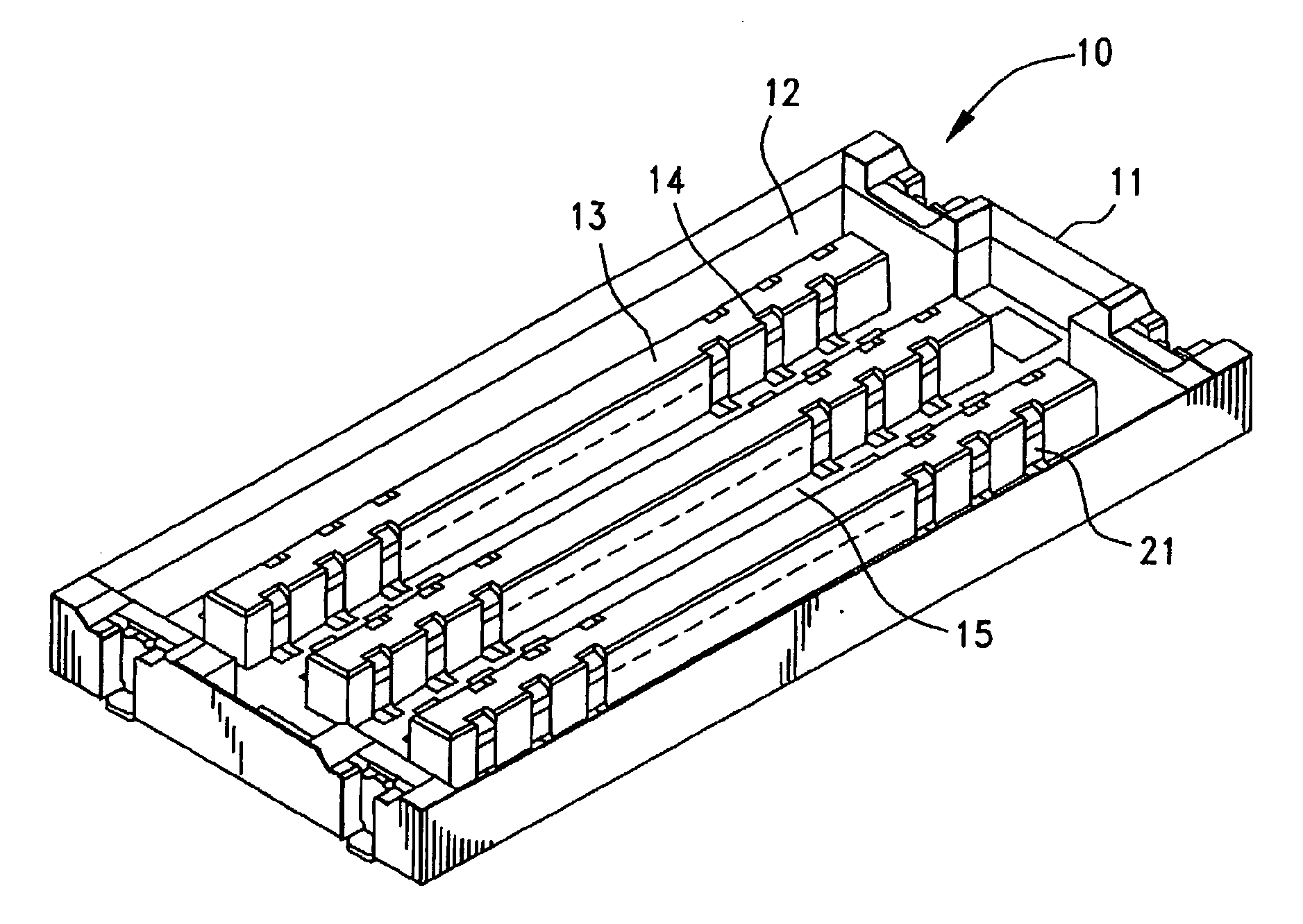
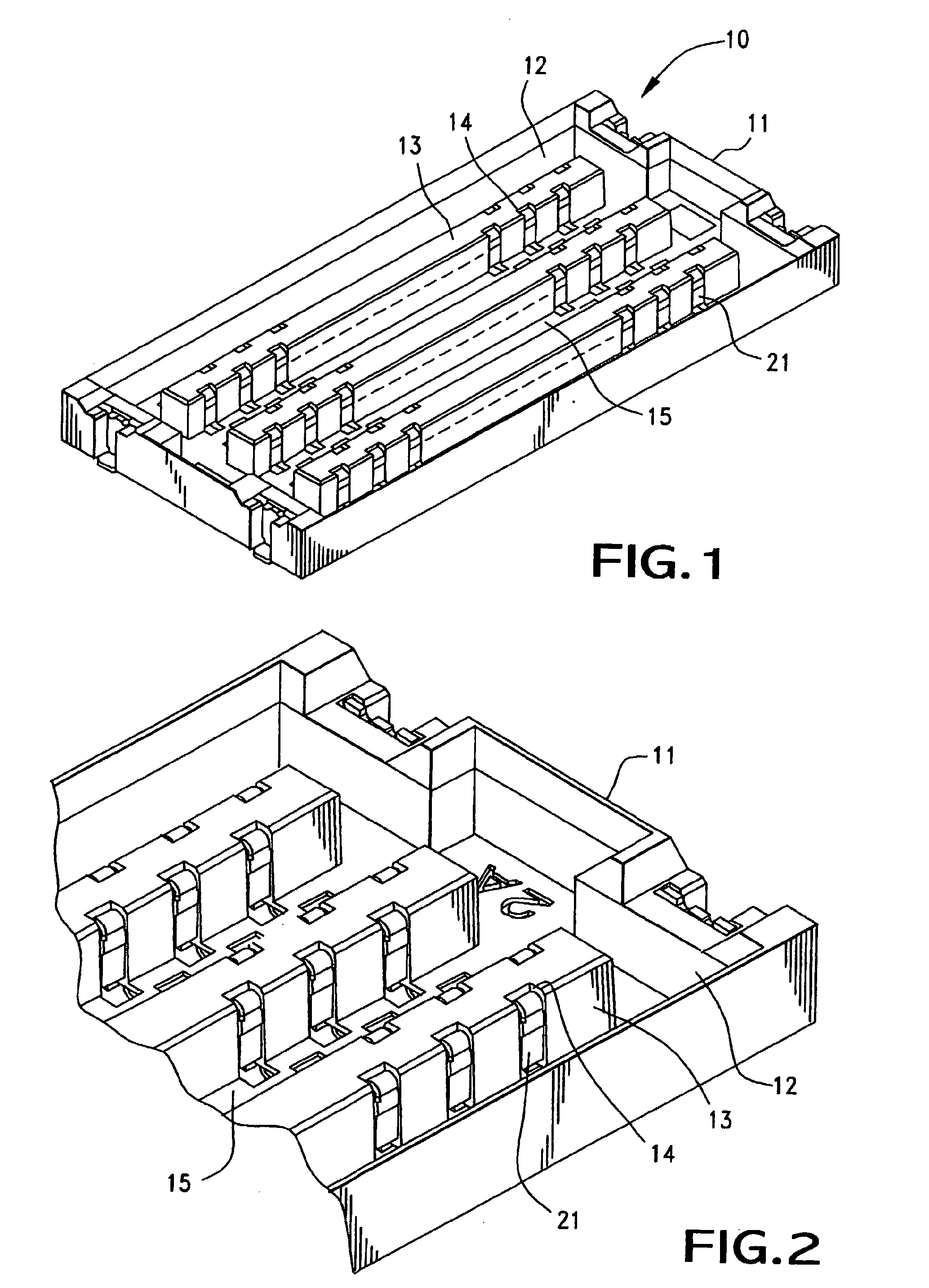
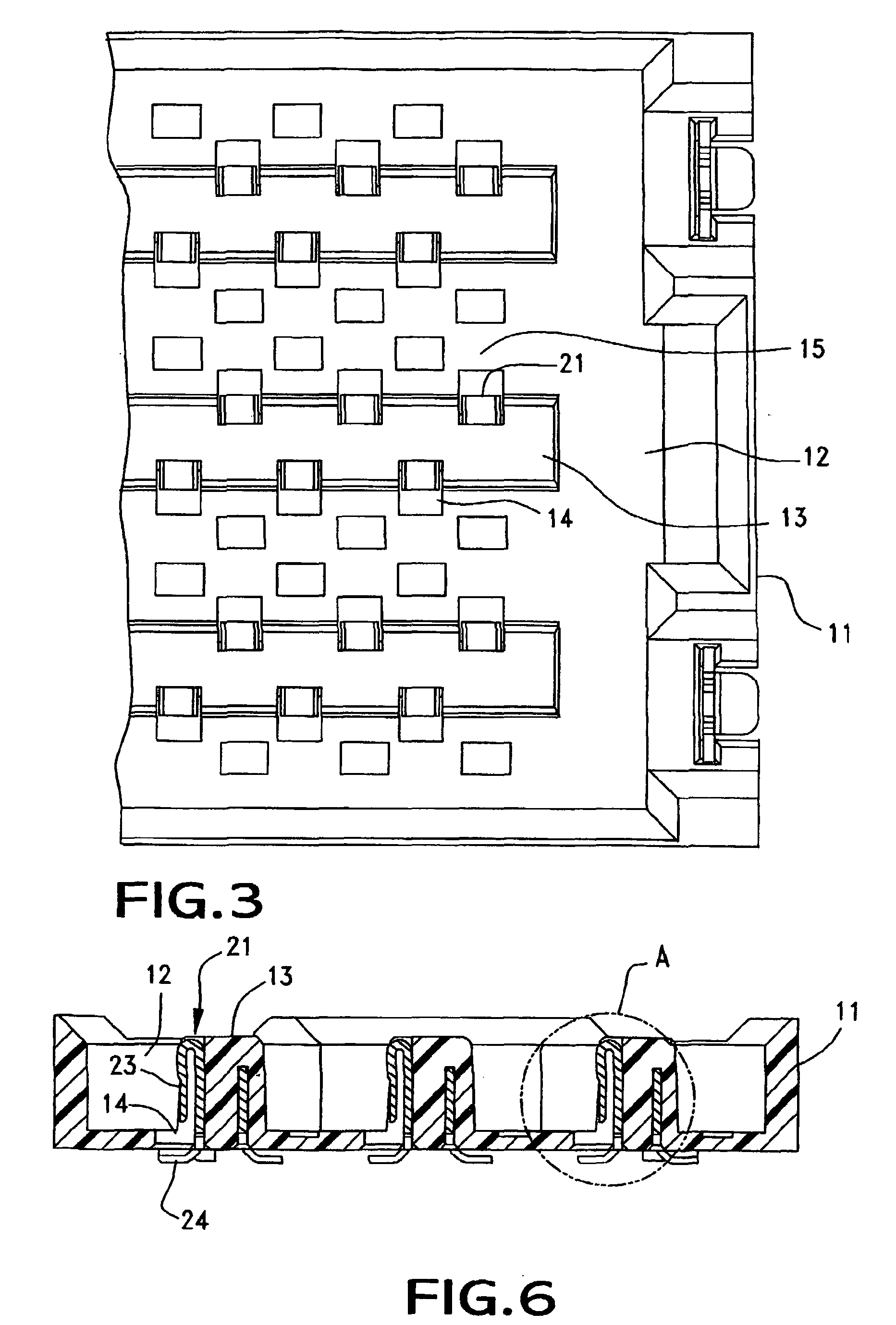
[0028]FIG. 1 is a perspective view of a first connector according to an embodiment of the present invention; FIG. 2 is an enlarged perspective view showing a main portion of the first connector according to the embodiment; and FIG. 3 is an enlarged plan view showing the main portion of the first connector according to the embodiment.

[0029]In these drawings, reference numeral 10 denotes a first connector, which is one of paired board-to-board connectors according to the present embodiment and which is a surface-mount-type connector to be mounted on a first circuit board 20 to be described later. The first connector 10 is inserted into a second connector 30, which is a counterpart connector and which will be described later. The second connector 30 is a surface-mount-type connector to be mounted on a second circuit board 40 to be described later. The board-to-board connectors a...


PUM


Abstract

A connector mountable to a printed circuit board is disclosed including a nonconductive housing with a plurality of slots, each slot having an opposed first and second end walls with grooves in each end wall and a plurality of terminals (41). Each terminal has a longitudinal axis, a retaining base (42), a solder portion (44), a resilient contact arm (43) and an alignment tab (45). The retaining base (42) has opposed edges with each edge fitting into a respective groove in the end walls holding each terminal to the non-conductive housing. The solder portion (44) extends from the retaining base (42) adjacent to the first end wall of the slot for soldering to the printed circuit board. The resilient contact arm (43) has opposed first and second sides extending from the retaining base (42), the first side of the arm is located adjacent the second end wall of the slot. The contact arm (43) is adapted to engage with a terminal (21) from a mating connector. The resilient contact arm and the solder portion (44) are offset from each other in a direction parallel to the longitudinal axis of the terminal. A locating tab (45) is stamped from the retaining base (42) with one end adjacent the second side of the resilient contact arm so that the second side of the resilient contact arm will engage the one edge of the locating tab if a side force is placed on the resilient contact arm (43) causing it to move away from the first side wall of the slot.

Description

FIELD OF THE INVENTION[0001]The present invention relates to a board-to-board connector.DESCRIPTION OF THE RELATED ART[0002]Conventionally, a board-to-board connector is used to electrically connect two parallel circuit boards together (see, for example, Japanese Patent Application Laid-Open (kokai) No. H10-125420). Such a board-to-board connector includes two connector sections which are respectively attached to mutually facing surfaces of two circuit boards and projects therefrom. The two connector sections are mated and connected with each other so as to establish electrical connection between the two circuit boards. In this case, each of the connector sections has a plurality of terminals whose tail portions are connected, through soldering, to wiring traces formed on the surface of the corresponding circuit board. When the connector sections are mated together, the terminals of one connector section come into contact with the corresponding terminals of the other connector secti...

Claims


Application Information

Patent Timeline
Patent Type & Authority Applications(United States)
IPC IPC(8): H01R12/22H01R12/00H01R12/51H01R12/55H01R12/71H01R12/78H01R12/79
CPCH01R23/68H01R12/73H01R12/57H01R13/20H01R12/00
Inventor MIZUMURA, AKINORI
Owner MOLEX INC
Why Eureka
Try Eureka