Radio communication system and method for communication between base station and antenna

a radio communication system and antenna technology, applied in the field of wireless communication, can solve the problems of limited access to the base station hardware (e.g. for maintenance purposes), difficulty in identifying antennas, and weaknesses of schemes, so as to simplify maintenance tasks, simplify the detection and analysis of failures, and increase the availability of the system and its base station

Inactive Publication Date: 2012-01-26
SIEMENS AG
View PDF1 Cites 20 Cited by
  • Summary
  • Abstract
  • Description
  • Claims
  • Application Information

AI Technical Summary

Benefits of technology

[0043]Compared to today's typical systems employing mostly passive antennas, embodiments of the present invention set a first filter at the base station side to overlay a DC/LF signal to an RF signal and transmit the overlaid signal to the antenna side, and set a second filter at the antenna side to recover the overlaid signal to obtain the DC/LF signal, thus providing a signaling channel between the base station and the antenna that can be used in various ways for simplifying maintenance tasks, allowing for a more comprehensive documentation and greatly simplifying the detection and analysis of failures or degradation of the RF signal path(s) between t

Problems solved by technology

Even access to the base station hardware (e.g. for maintenance purposes) may be restricted.
For example, in Communication Based Train Control (CBTC) systems, particularly in Mass Transit scenarios, base stations are typically installed close to the track and not accessible during hours of train operation.
Therefore, identification of antennas may sometimes be complicated.
The scheme has some weaknesses due to the inherent transmission over-the-air and is also limited with respect to the identification of the faulty components, i.e. the localization of problems.
1. For reference purposes and post-installation troubleshooting and maintenance, it is desirable to maintain comprehensive documentation of the hardware components (e.g. antennas) used and of their characteristics and performance figures as measured before/during the installation. In principle this documentation could be based on a unique serial number printed on each component or attached to it in an electronically readable form, such as barcode or RFID tag. Since antennas cannot easily be accessed after installation, however, it will be hard to read the attached labels printed on the antennas or attached in an electronically readable form when for example it is required to verify correct assignment of antenn

Method used


Image

  • Radio communication system and method for communication between base station and antenna
  • Radio communication system and method for communication between base station and antenna
  • Radio communication system and method for communication between base station and antenna

Examples


Embodiment Construction

[0052]To make the objective, technical solution and merits of the present invention clearer, the present invention is described hereinafter with reference to the following embodiments.

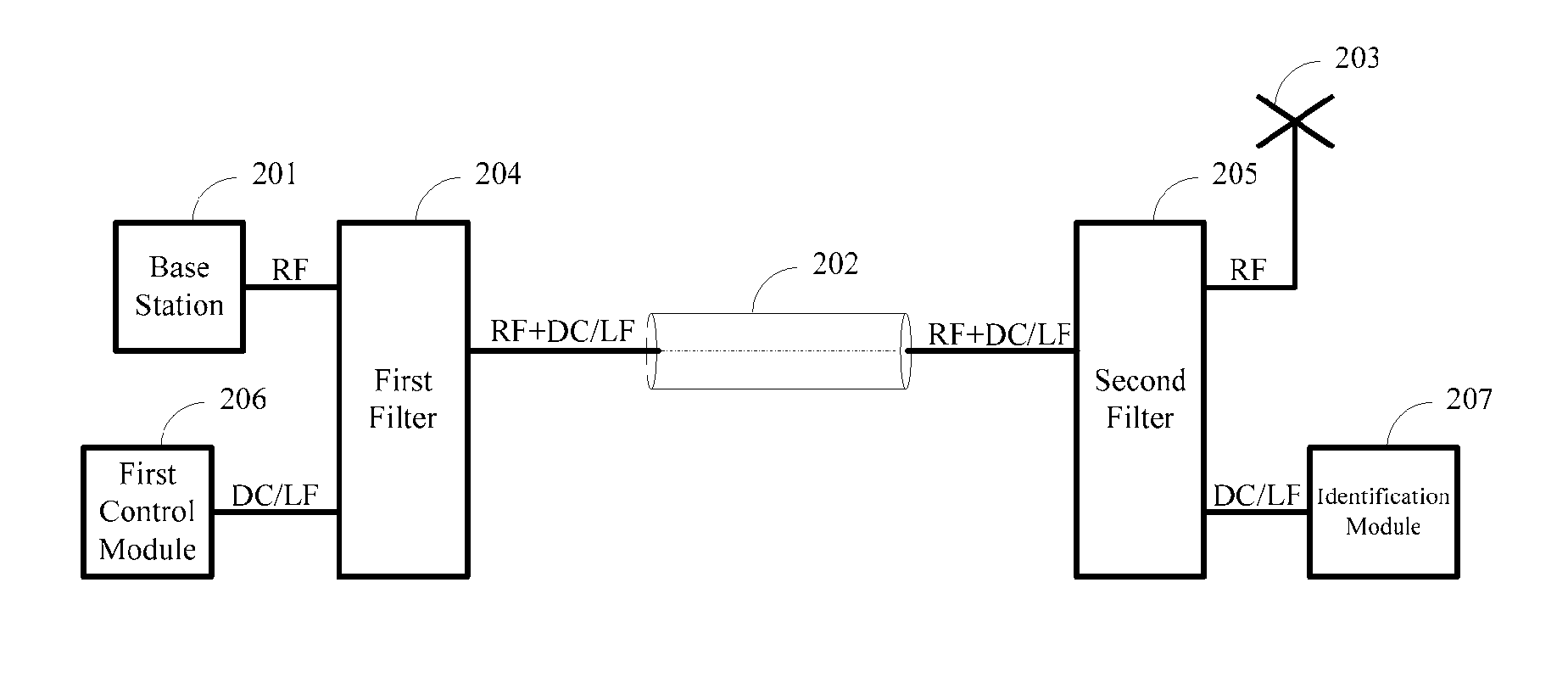
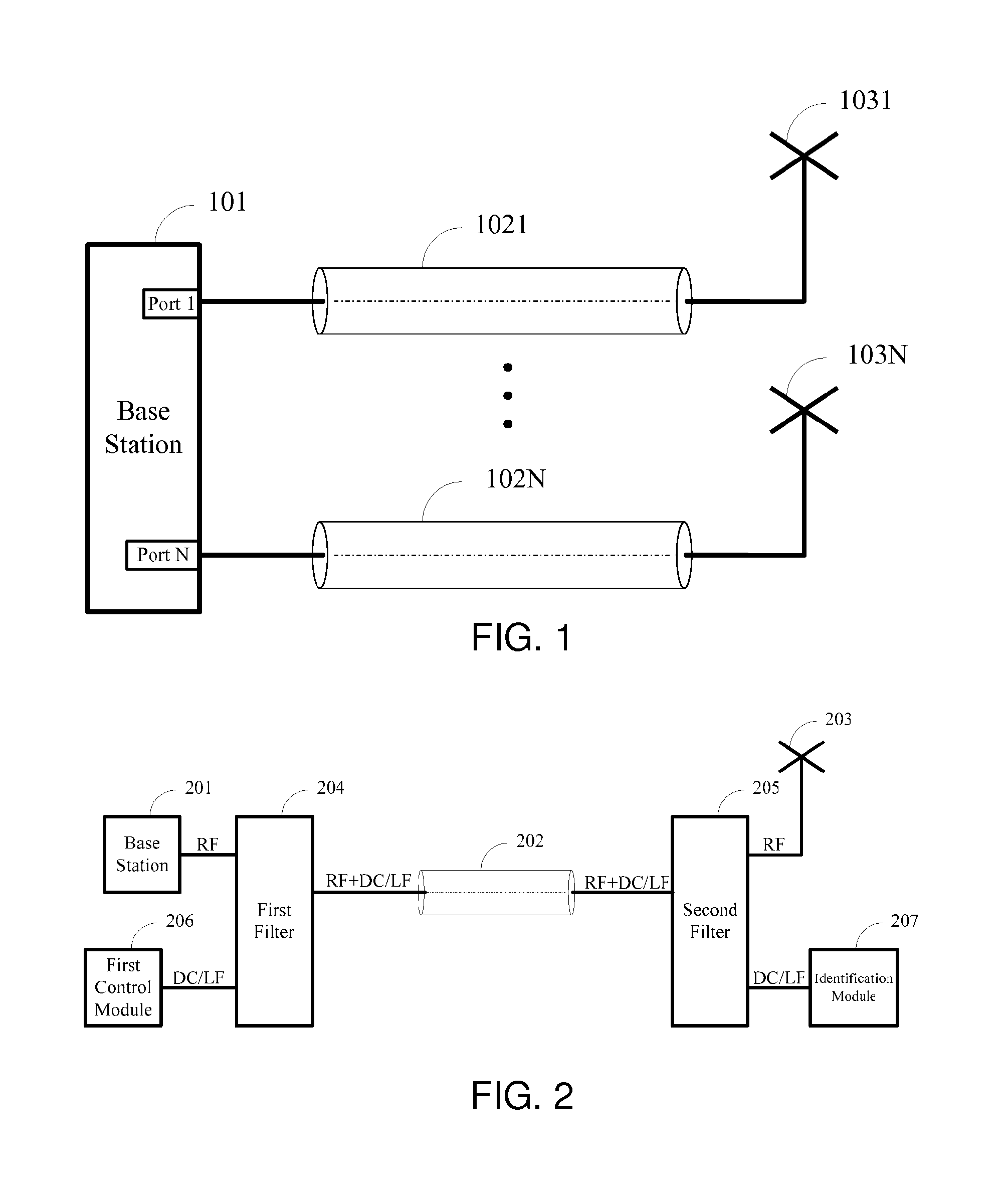
[0053]Referring to FIG. 2, embodiments of the invention make use of a technique of coupling direct current (DC) or low frequency (LF) signals into an RF cable in addition to an RF signal from a different source. Specifically, the RF signal provided from an RF port of a base station 201 and the DC / LF signals provided by a first control module 206 are inputted to a first filter 204, wherein the first control module 206 may be a source other than the base station 201. Thereafter, the first filter 204 combines them into a single output signal (i.e., an RF+DC / LF signal) and transmits the RF+DC / LF signal to a second filter 205 through an RF cable 202. Specifically, the first filter 204 connects with a first end of the RF cable 202, and the second filter 205 connects with a second end of the RF cable 202. The...


PUM


Abstract

A radio communication system has a base station and one or more antennas, each of the one or more antennas connects with a radio frequency port of the base station through an RF connection. Direct current and/or low frequency (DC/LF) signals are transmitted to an antenna via the RF connection corresponding to the antenna. The radio communication system further has an identification module at the antenna side, adapted to give an indication for identification of the antenna when receiving the DC/LF signals from the RF connection. Accordingly, the information exchange between the base station and a more or less intelligent “identification unit” in the antenna is performed to allow identification of the antenna from the base station side and further allow diagnosis of the cable link.

Description

FIELD OF THE INVENTION[0001]This invention relates to wireless communications, and more particularly, to a radio communication system and a communication method between a base station and antennas for identification of the antennas and diagnosis of radio frequency (RF) components.BACKGROUND OF THE INVENTION[0002]In wireless communication systems, particularly in outdoor scenarios (e.g. cellular communication systems, vehicle-to-wayside data communication, etc.) each radio base station may be equipped with several antennas which might be spatially separated by some distance from the base station hardware. Here, the term base station used throughout this invention generally refers to the transmitting / receiving entities of the stationary radio network infrastructure. That is, the term base station also covers Access Points of WLAN based systems, Radio Gateways of Wireless Sensor Networks, etc.[0003]The antennas will typically be mounted in places that cannot easily be accessed, e.g. on...

Claims


Application Information

Patent Timeline
IPC IPC(8): H04B7/24
CPCH04W88/085H04B1/18
Inventor KISTER, ANDREASLAMPE, MATTIAS
Owner SIEMENS AG
Why Eureka
Try Eureka