Adjustable cable machine

a cable machine and adjustable technology, applied in the field of cable machines, can solve the problems of high product cost, difficult assembly, and difficult transportation and placement, and achieve the effects of reducing production and transportation costs, preventing injuries, and reducing parts

Inactive Publication Date: 2012-01-26
HSIUNG BOB
View PDF7 Cites 36 Cited by
  • Summary
  • Abstract
  • Description
  • Claims
  • Application Information

AI Technical Summary

Benefits of technology

[0006]Therefore, a novel cable machine is provided herein which takes up a limited space, requires fewer parts, and reduces production and transportation costs.
[0007]Another major objective of the present invention is to provide an adjustable cable machine capable of offering additional exercising styles, satisfying the needs of various users, preventing the chances of injuries, and enhancing the exercising effects.
[0008]To achieve the above objectives, the present invention's handles are hung from extension rods that could be pivotally turned behind the seat member. As such, the handles could be raised high above the seat member or lowered low to the lateral sides of the seat member. The cable machine therefore offers versatile exercising styles, with a simplified structure and reduced dimension for easier and low-cost transportation and storage.

Problems solved by technology

Together with the expanded lateral space required by the swing elements as in the prior art, the cable machine takes up a significantly sizable space, making it very difficult for transportation and placement.
In addition, the cable machine usually has a complex structure, thereby leading to high product cost and difficult assembly.
Further more, the conventional cable machine only offers limited exercising styles, failing to satisfy various users' needs.
A user could easily get bored after a short while.
For a user with a posture not quite compatible with the design of the cable machine, the user could be easily injured.

Method used


Image

  • Adjustable cable machine
  • Adjustable cable machine
  • Adjustable cable machine

Examples


Embodiment Construction

[0020]The following descriptions are exemplary embodiments only, and are not intended to limit the scope, applicability or configuration of the invention in any way. Rather, the following description provides a convenient illustration for implementing exemplary embodiments of the invention. Various changes to the described embodiments may be made in the function and arrangement of the elements described without departing from the scope of the invention as set forth in the appended claims.

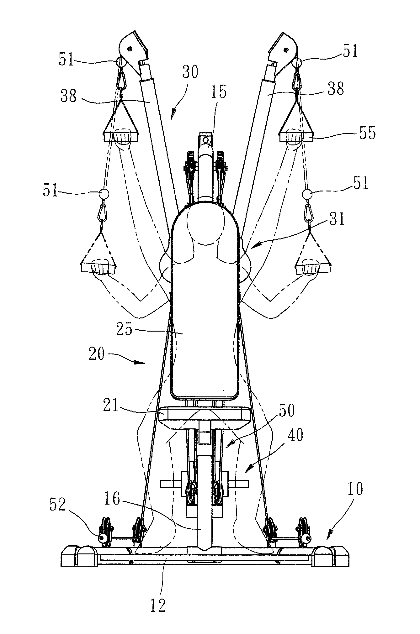
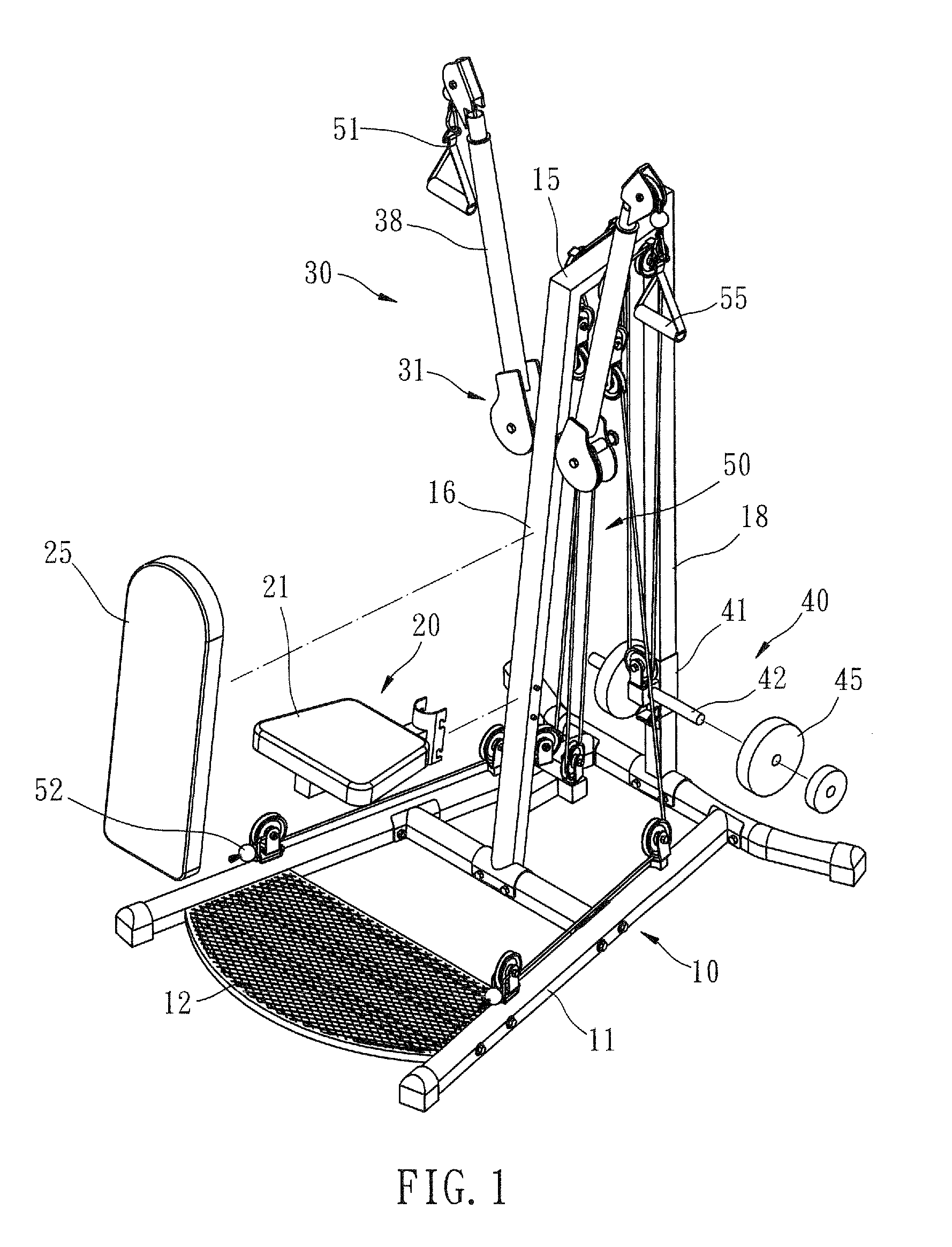
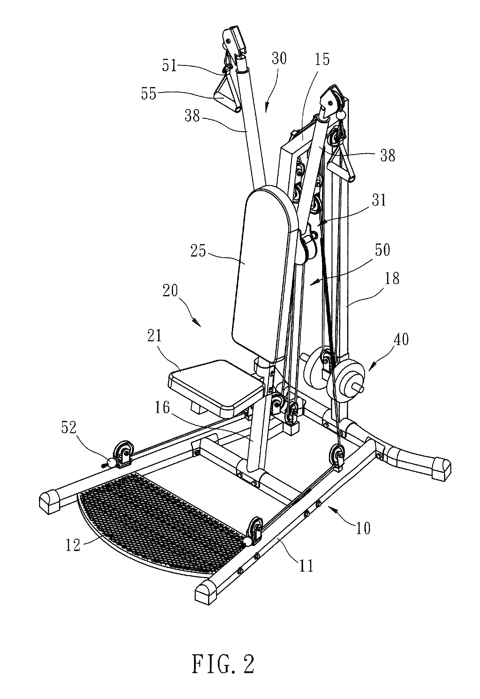
[0021]As shown in FIGS. 1 to 3, a cable machine according to an embodiment of the present invention contains a base member 10, a frame member 15, a seat member 20, two extension members 30, a weight member 40, and a traction member 50.

[0022]The base member 10 is roughly shaped like an inversed “A” with two ground bars 11 roughly in parallel but spaced wider apart as they are extended towards a front direction of the cable machine to provide a solid ground support to the cable machine. A footboard 12...


PUM


Abstract

The adjustable cable machine contains a frame member raised on a base member having two ground bars. A seat member is configured in the front and a weight member capable of sliding vertically on the frame member. Two extension members are configured oppositely to the lateral sides of the frame member. Each extension member contains an adjustment element fixed to the frame member and an extension rod pivotally joined to the adjustment element. Each extension rod could be turned to adjust its angle relative to the frame member. A traction member composed of pulleys and cables is configured between the weight member and the extension members. A handle could be configured to an upper actuating ends at a top end of each extension rod or a lower actuating end in a front section of a ground bar.

Description

(a) TECHNICAL FIELD OF THE INVENTION[0001]The present invention generally relates to cable machines for weight and functional trainings, and more particular to an adjustable cable machine to fit the needs of various users.(b) DESCRIPTION OF THE PRIOR ART[0002]A cable machine is used in weight training or functional training. It allows a user to pull a weight stack by the arms so as to exercise the arm muscle. A cable machine usually contains a frame, a seat member on the frame, a weight member on the frame, a traction member on the frame composed of pulleys and cables, and handles above the seat member connecting to the traction member's actuating ends. As such, a user could sit on the seat member and pull the handles downwards by the arms to overcome the resistance rendered from the weight member through the traction member. Taiwan Patent No. M364523 teaches a cable machine further providing left and right swing elements connected to the traction member for different exercising sty...

Claims


Application Information

Patent Timeline
Patent Type & Authority Applications(United States)
IPC IPC(8): A63B21/06
CPCA63B21/062A63B21/151A63B2208/0233A63B23/12A63B23/1245A63B21/156A63B21/0628A63B23/1209A63B23/03541A63B23/1272A63B21/4043A63B21/4035
Inventor HSIUNG, BOB
Owner HSIUNG BOB
Why Eureka
Try Eureka