Structure of a Cutting Tool

a cutting tool and tool structure technology, applied in the field of hand tools, can solve the problems of imperfect holding effect, and achieve the effects of improving the holding effect, improving the structure of the cutting tool, and being easy to assembl

Active Publication Date: 2012-02-02
ASIAN FIRST REFRIDGERATOR
View PDF23 Cites 8 Cited by
  • Summary
  • Abstract
  • Description
  • Claims
  • Application Information

AI Technical Summary

Benefits of technology

[0007]One objective of the invention is to provide an improved structure of a cutting tool having a simpler structure, easier to assemble, and providing a better pipe positioning effect.
[0008]Another objective of the invention is to provide an improved structure of a cutting tool for quickly holding a pipe.

Problems solved by technology

Such a holding effect is not perfect.

Method used


Image

  • Structure of a Cutting Tool
  • Structure of a Cutting Tool
  • Structure of a Cutting Tool

Examples


Embodiment Construction

[0018]The present invention will be apparent from the following detailed description, which proceeds with reference to the accompanying drawings, wherein the same references relate to the same elements.

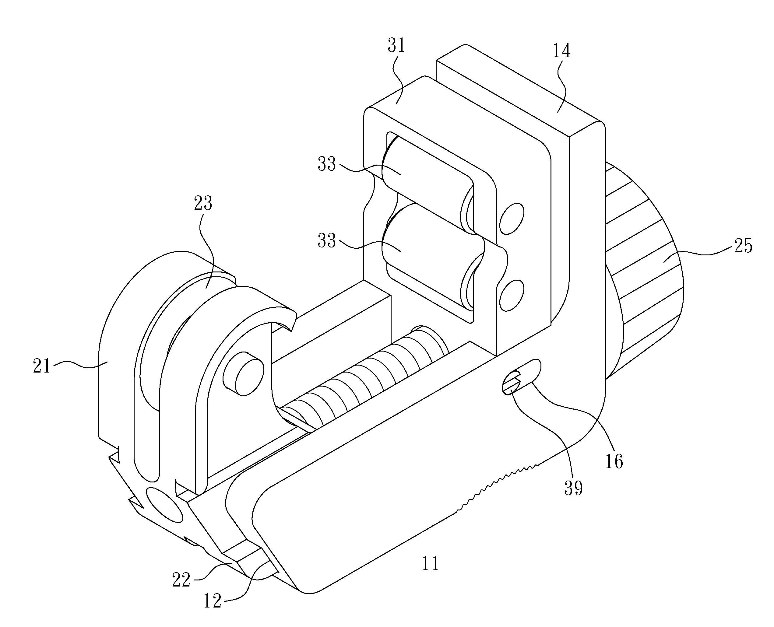
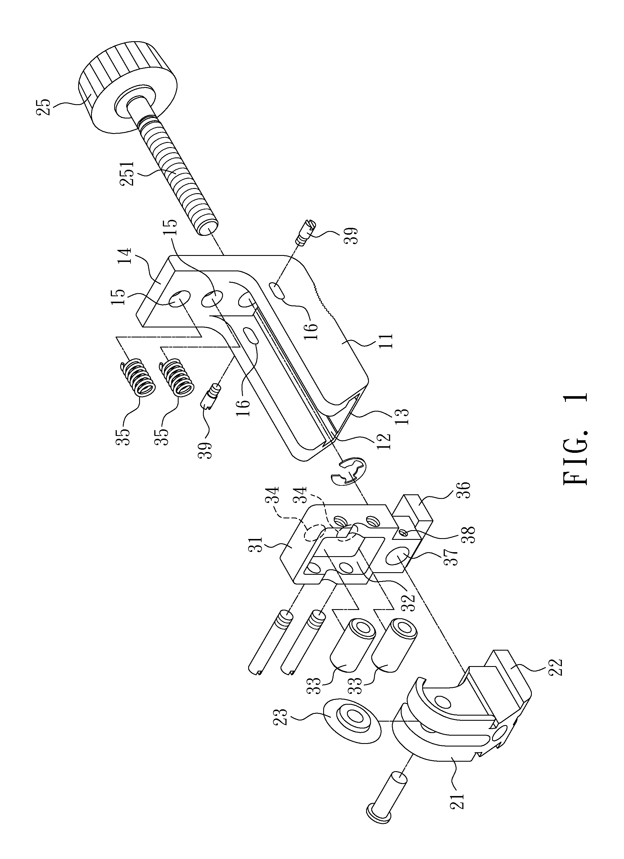
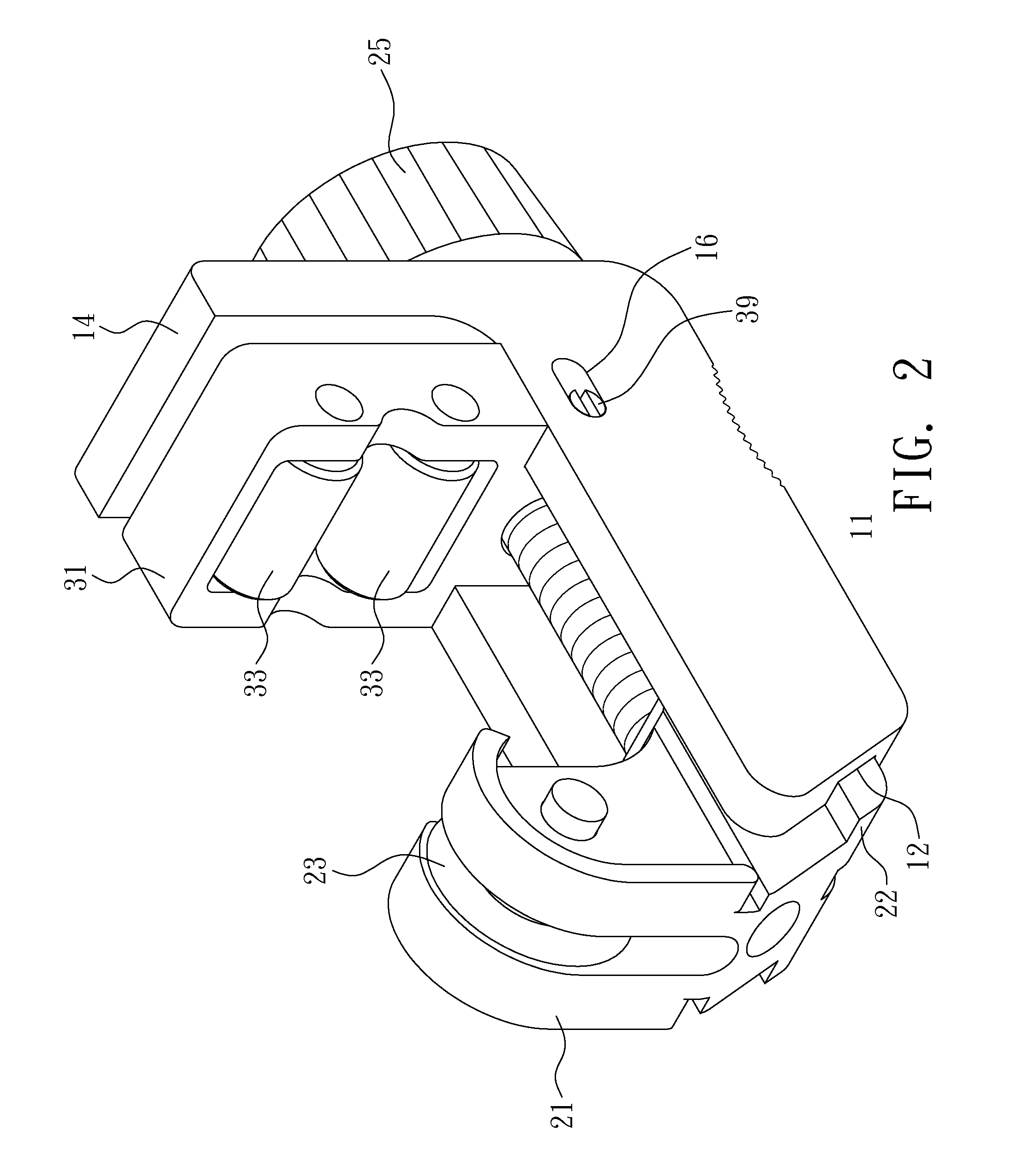
[0019]Please refer to FIGS. 1 to 3. An improved structure of a cutting tool according to the invention includes a body 11, a moving base 21, and a roller base 31.

[0020]The bottom of the body 11 has a track groove 12 extending in the transverse direction. One side of the track groove 12 is formed with an opening in communications with the exterior. The other side is extended upward with a stopping wall 14. The end surface of the stopping wall 14 facing the track groove 12 is formed with two recesses 15. A sliding groove 16 is formed on the two sidewalls of the body 11 opposite to the track groove 12.

[0021]The bottom of the moving base 21 is formed with a sliding part 22 to be mounted in the track groove 12. The moving base 21 slides in the track groove 12 of the body 11 via the sliding...


PUM

PropertyMeasurementUnit
structureaaaaaaaaaa
driving forceaaaaaaaaaa
elasticaaaaaaaaaa

Abstract

An improved structure of a cutting tool includes a body, a moving base, and a roller base. The body has a track groove whose one side is extended upward with a stopping wall. The moving base is disposed to slide in the track groove and mounted with a cutting wheel. The moving base is connected with a transmission element so as to move along the track groove. The roller base is disposed between the moving base and the stopping wall. More than one elastic element is disposed between the roller base and the stopping wall. The elastic elements generate a deviation when the roller base is under a force. The roller base has at least two rollers corresponding to the cutting wheel.

Description

BACKGROUND OF THE INVENTION[0001]1. Field of Invention[0002]The invention relates to a hand tool for cutting pipes and, in particular, to an improved structure of the cutting tool.[0003]2. Related Art[0004]FIG. 5 shows a conventional pipe cutting tool. By turning a knob 51, a rolling blade 52 moves toward two rollers 53 to hold a pipe 54. As one keeps turning the knob 51, the rolling blade 52 then exerts a force and cuts through the pipe 54.[0005]However, the rollers 53 are fixed on one side of the cutting tool in this conventional structure. Therefore, it provides only one holding position that cannot be fine-tuned by the user according to the size of the pipe 54 or the magnitude of the imposed force. Such a holding effect is not perfect. When the rolling blade 52 and the two rollers 53 cannot accurately hold and position the pipe 54, it becomes harder for cutting. More dangerously, the pipe 54 may slip out of the rolling blade 52 and the two rollers 53.SUMMARY OF THE INVENTION[000...

Claims


Application Information

Patent Timeline
Patent Type & Authority Applications(United States)
IPC IPC(8): B23D21/08
CPCB23D21/08
Inventor CHIU, JACKCHIU, SHENG-CHIH
Owner ASIAN FIRST REFRIDGERATOR
Why Eureka
Try Eureka