
Lantern planter

a planter and lantern technology, applied in the field of lantern planters, can solve the problems of difficult to adjust to changing season conditions, difficult to move around, and difficult to disassemble support structures of this type, and achieve the effects of convenient user adjustment, improved lighting, and easy movemen

Inactive Publication Date: 2012-02-02
MARANO TAMARA
View PDF0 Cites 4 Cited by
  • Summary
  • Abstract
  • Description
  • Claims
  • Application Information

AI Technical Summary

Benefits of technology

[0014]One advantage of the present invention is that the planter vessel can accommodate different styles of illumination devices that can be easily changed by the user. The user can select a solar-powered device for one type of outdoor event or pick a hydrocarbon fuel type device for purposes of providing illumination and insect repellant. Or depending on the application of the user, an illumination device that has a candle installed could be very desirable by the user.
[0015]Yet another advantage of the present invention is the planter vessel can be easily moved around the outdoor living area by the user. This allows the user to accommodate changing natural lighting conditions as the seasons change. The user can also move the planter vessel around to accommodate different life activities such as dances, outdoor dining, game playing, and other activities that would be improved by better lighting.
[0016]Yet another advantage of the present invention is that the planter vessel can have the illumination device removed altogether and have another device affixed atop the pole. These devices could include a rope holder for purposes that a plurality of planter vessels could be organized so that when the rope holder is affixed atop the post and a rope is installed, the user constructs a cordoned off area or directs human traffic flow for outdoor life activities that call for such control. Besides the rope holder, a drink holder could be affixed such that multiple users could place their beverages atop the drink holder. This allows the planter vessel to be a very useful accessory for the user when they are hosting parties. Besides the drink holder, a sign holder can be installed by the user that would hold a variety of different placard-style signs that would provide information to users and their guests. In addition, the sign holder can be replaced with a cigarette butt holder that the user, or their guests, can use to properly dispose of their cigarette butts and ashes instead of displacing the waste onto the user's landscape surfaces. Lastly, the user can install atop the post an umbrella that can provide shading for the user, the user's guests, and / or pets.
[0017]Yet another advantage of the present invention is that the lantern planter can be made in a wide-range of styles and sizes such that the lantern planter could be placed atop a landscaping surface or atop a table. This particular feature of the present invention provides more diversity in the available applications of the present invention.

Problems solved by technology

Support structures of this sort are problematic in that they are easily dislodged due to natural environmental elements, people and animals traversing by the support and making contact with the same and knocking the support askew.
The problem associated with these types of support structures is that they cannot be easily moved around to accommodate changing season conditions, activities of the user such as hosting parties, games and other outdoor events, without leaving holes in the solid-surface landscaping element from the removal of the mechanical fasteners.

Method used


Image

  • Lantern planter
  • Lantern planter
  • Lantern planter

Examples


second embodiment

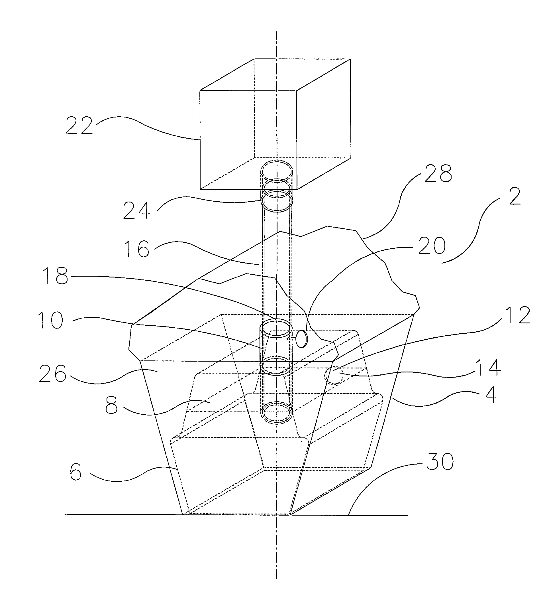
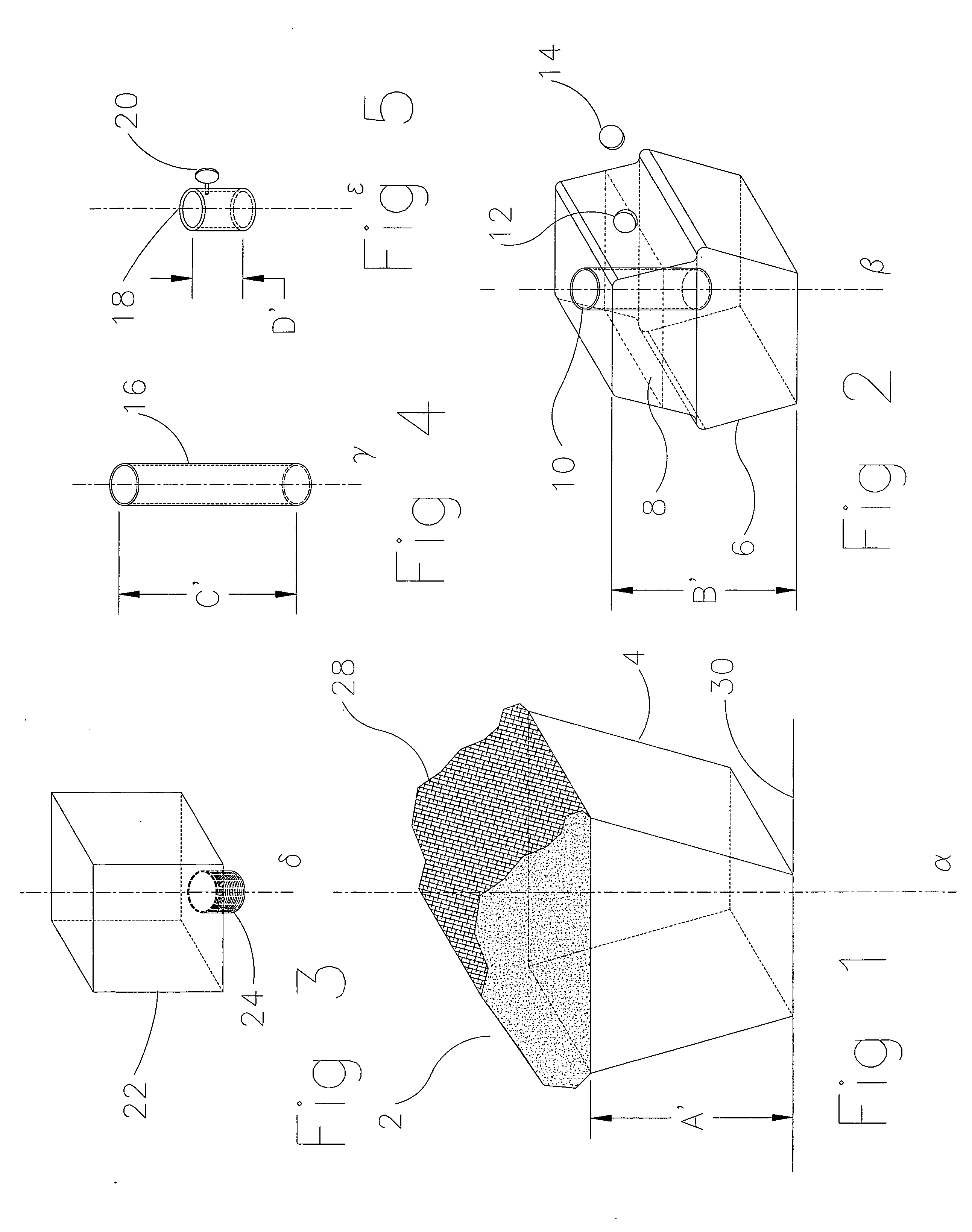
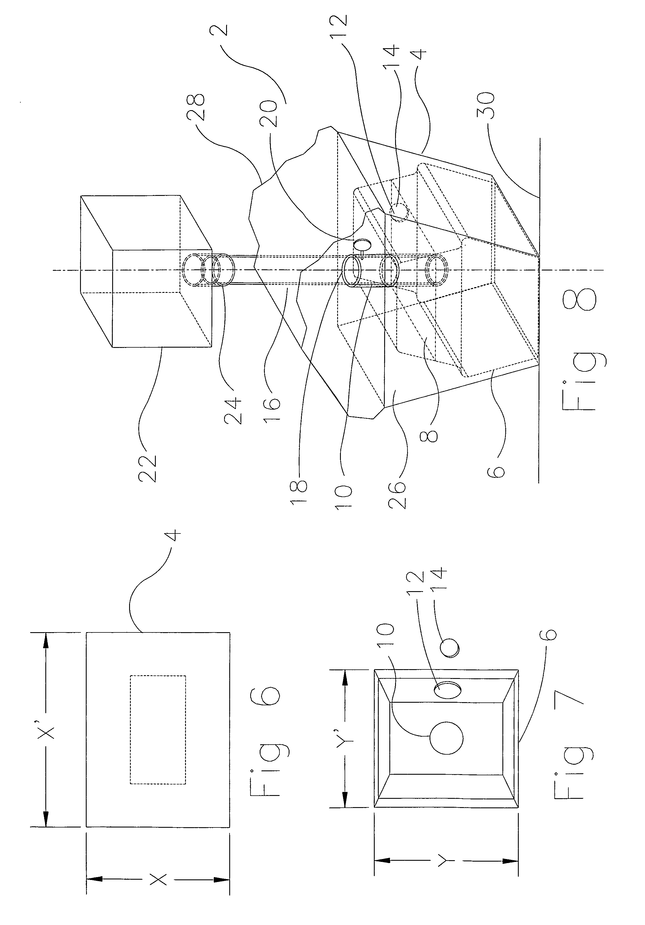
[0058]Now additionally referring to FIG. 9, what is shown is a perspective view of the present invention, namely the exterior vessel 4 and the interior vessel 6 are constructed in a manner that they are a unified piece instead of having a separate exterior vessel 4 and interior vessel 6. An interior vessel 6 is created in the interior of the exterior vessel 4 and holds the interior fill material 8. Traversing through the second end of the interior vessel 6 through the center point of the second end of the exterior vessel 4 is the post hole 10 containing the same characteristics as demonstrated and discussed in the preferred embodiment of the present invention. Also contained in the interior vessel wall is the fill hole 12 and fill hole cap 14 containing the same characteristics as demonstrated and discussed in the preferred embodiment of the present invention. Atop the second end of the interior vessel 6 is the exterior fill material 26 and atop that is the decorative material 28. T...

third embodiment

[0059]Now additionally referring to FIG. 10, what is shown is a perspective view of the present invention namely that the exterior vessel 4 and the interior vessel 6 are two separate pieces as previously discussed. The shape of the exterior vessel 4 and the interior vessel 6 are distinctly conical in shape with the first end of the external vessel 4 having a smaller cross-sectional area than the second end of the external vessel 4. Likewise, the first end of the internal vessel 6 has a smaller cross-sectional area than the second end of the internal vessel 6.

[0060]Now additionally referring to FIG. 11, what is shown is a perspective view of a fourth embodiment of the present invention in that there is a unified configuration of the external vessel 4 and internal vessel 6, as demonstrated and discussed for the second embodiment of the present invention and shown in FIG. 9. This embodiment takes on a shape of that being conical having the same characteristics as demonstrated and discu...

fourth embodiment

[0063]Now additionally referring to FIG. 14, what is shown is the supported device 22. In this embodiment, the user installs the supported device 22 atop the second end of the post 16 via the support device hole 24 located on the first end of the supported device 22. There is provided on the second end of the supported device 22 a cigarette butt holder 36 so that one or more tobacco-related items can be placed into the cigarette butt holder 36 while being consumed / enjoyed by the user.


PUM


Abstract

A lantern planter wherein an exterior vessel contains inside of it an interior vessel. The interior vessel contains an interior fill material utilized to create mass inside the present invention. Affixed atop the interior vessel is a post support collar used to provide support to a post that is used to provide vertical support and stability to a supported device mechanically fastened to the post. The interior vessel, once filled with the interior fill material, and after the post is inserted via the post support collar has exterior fill material and decorative material installed atop the interior vessel such that the lantern planter provides structural support for the supported device and is aesthetically pleasing to the user.

Description

CROSS-REFERENCE TO RELATED APPLICATIONS[0001]This is a non-provisional patent application bearing the title “LANTERN PLANTER” filed on Jul. 28, 2010.BACKGROUND OF THE INVENTION[0002]1. Field of the Invention[0003]The present invention relates to planter vessel, and more particularly a planter vessel that has been constructed to provide stability and support to various outdoor decorative objects that the user would operate to provide luminescence and decorative design elements in and throughout their living spaces.[0004]2. Description of the Related Art[0005]There are numerous planter vessels and support structures available in the market that only serve a solitary function, i.e. to either act as a planter for various types of flora, or to serve as a mounting point on a solid-surface landscaping element such as concrete, pavement, or landscaping timbers and is used to support a lighting device affixed to a pole or hanger. With the economy in the state that it is, people are spending ...

Claims


Application Information

Patent Timeline
Patent Type & Authority Applications(United States)
IPC IPC(8): A01G9/02
CPCA01G9/02
Inventor MARANO, TAMARA
Owner MARANO TAMARA
Learn More