
Waste heat air conditioning system

Inactive Publication Date: 2012-02-02
LINUM SYST
View PDF5 Cites 27 Cited by
  • Summary
  • Abstract
  • Description
  • Claims
  • Application Information

AI Technical Summary

Benefits of technology

[0006]In view of the discussion provided above and other considerations, the present disclosure provides methods and apparatus to overcome some or all of the disadvantages of prior and present method

Problems solved by technology

Many industrial processes produce waste heat of low temperature, typically less than 150° C., which is typically too low to be used to accomplish useful work.
Unfortunately, the absorption refrigeration cycles typically used suffer from inefficiency, and are typically unable to achieve a thermal coefficient of performance (COP) greater than about 0.7, where the term COP is defined as ΔQcold / ΔQin, where ΔQcold is defined as the change in heat of the load and ΔQin is defined as the heat consumed by the cooling system.
Furthermore, current state of the art waste heat driven A / C systems, such as absorption chillers utilizing the absorption refrigeration cycle, are incapable of operating in the absence of sufficient waste heat, and therefore require a complete additional system for backup.
Disadvantageously, the system of Benson requires, inter alia, a five way valve which adds to cost and complexity.
Furthermore, the system of Benson exhibits a low overall COP, is incapable of operating in the absence of waste heat on residual power and is operative at temperatures of about 200° C., (400° F.) which increases cost.

Method used


Image

  • Waste heat air conditioning system
  • Waste heat air conditioning system
  • Waste heat air conditioning system

Examples


Embodiment Construction

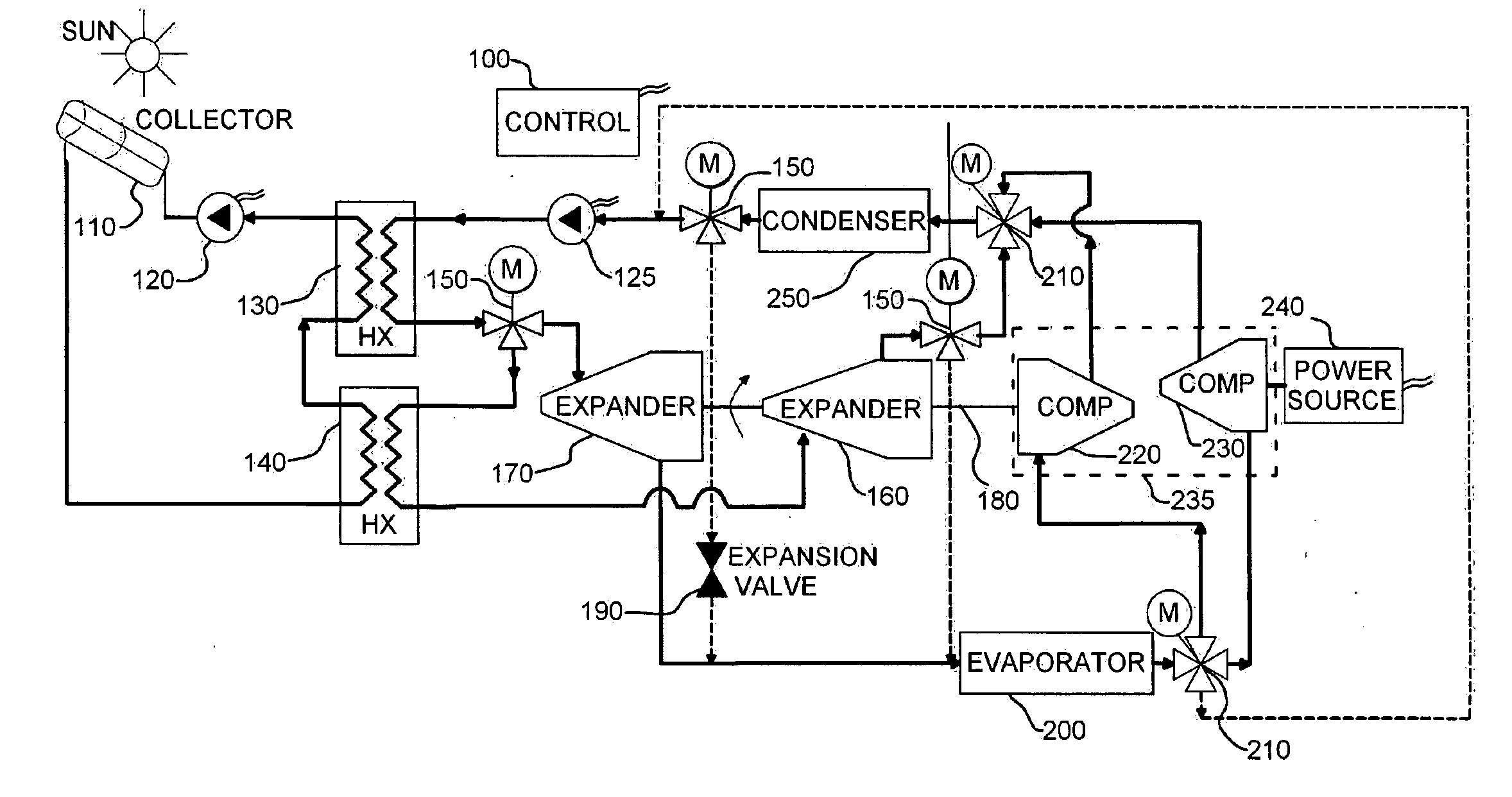
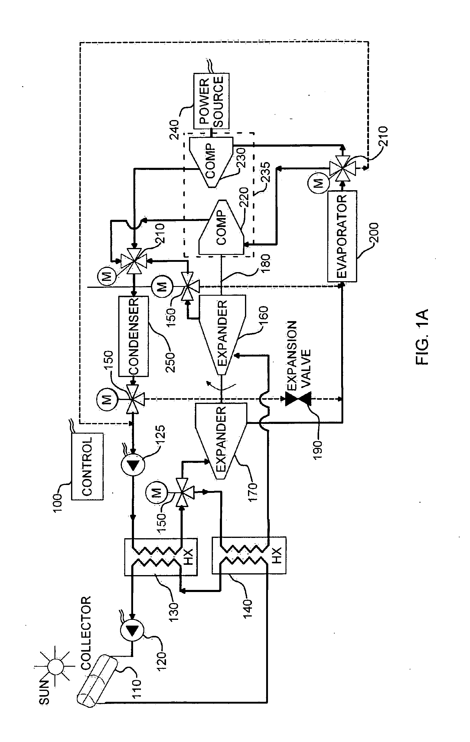
[0037]Before explaining at least one embodiment in detail, it is to be understood that the invention is not limited in its application to the details of construction and the arrangement of the components set forth in the following description or illustrated in the drawings. The invention is applicable to other embodiments or of being practiced or carried out in various ways. Also, it is to be understood that the phraseology and terminology employed herein is for the purpose of description and should not be regarded as limiting. In particular, the term connected as used herein is not meant to be limited to a direct connection, and allows for intermediary devices or components without limitation. Three way, four way and five way valves are shown as single elements for simplicity, but may be comprised of a plurality of cooperating valves without exceeding the scope.

[0038]FIG. 1A illustrates a high level block diagram of a first exemplary embodiment of an apparatus arranged to provide a...


PUM


Abstract

The present disclosure provides for a method and apparatus of providing air conditioning from a waste heat source. A vapor state expander is provided producing mechanical work, and a compressing unit is at least partially operative responsive to the mechanical work output of the vapor state expander. In another exemplary embodiment a second liquid state expander producing mechanical work is further provided, the compressing unit operative further responsive to the mechanical work of the liquid state expander. The apparatus disclosed is further capable of providing backup heating and cooling from an additional power source when the waste heat source is insufficient.

Description

CROSS-REFERENCE TO RELATED APPLICATIONS[0001]This application claims priority from U.S. Provisional Patent Application Ser. No. 61 / 165,533 filed Apr. 1, 2009, of the above name, the entire contents of which are incorporated herein by reference.TECHNICAL FIELD[0002]The present disclosure relates generally to the field of air conditioning and in particular to a system and method for providing air conditioning from waste heat preferably utilizing a combination of a liquid phase expander and a vapor phase expander.BACKGROUND ART[0003]Many industrial processes produce waste heat of low temperature, typically less than 150° C., which is typically too low to be used to accomplish useful work. Certain thermodynamic cycles, such as absorption refrigeration, can provide environmental cooling from low grade heat sources. Similarly, solar thermal energy received in a solar collector such as a concentrating type or an evacuated tube type is typically of the order of waste heat, and has been empl...

Claims


Application Information

Patent Timeline
IPC IPC(8): F25B1/00
CPCF24F5/0046F25B9/06F25B2400/075F25B27/002F25B11/02F25B27/02F25B49/022F25B41/20
Inventor BERSON, YUVALHIRSHFELD, AMIR
Owner LINUM SYST
Learn More