Movable base with wheels deployable by cyclic driving assembly

a technology of cyclic driving assembly and supporting base, which is applied in the direction of child seats, mechanical control devices, instruments, etc., can solve the problem of inconvenient use of the mechanism

Active Publication Date: 2012-02-02
OLIVER JOEN AN MA
View PDF12 Cites 59 Cited by
  • Summary
  • Abstract
  • Description
  • Claims
  • Application Information

AI Technical Summary

Benefits of technology

[0007]One aspect of the inventions is to provide a movable base that is easy to move between configurations where the wheels are either deployed or retracted. For example, in one embodiment a base assembly comprises a load supporting frame, a circular ratcheting gear, a first ratcheting pawly, an elongated member, and a linkage. The load supporting frame can have one or more wheels movable between deployed and undeployed positions. The circular ratcheting gear can rotatably mount to the load supporting frame and have a plurality of teeth and an eccentric opening within the circular ratcheting gear. The first ratcheting pawl can couple to the load supporting frame adjacent the ratcheting gear to form a ratcheting relationship with the ratcheting gear. The ratcheting relationship can substantially allow rotation of the ratcheting gear in only a first direction relative to the first ratcheting pawl. The elongated member can pivotably mount within the opening. The elongated member can have a second ratcheting pawl mounted to the elongated member adjacent to the ratcheting gear to form a ratcheting relationship with the ratcheting gear. The ratcheting relationship can substantially allow rotation of the ratcheting gear in only the first direction relative to the second ratcheting pawl. The linkage can be pivotably mounted within the opening and pivotably mounted to one or more of the wheels. Pivoting of the elongated member in one direction can cause a rotation of the ratcheting gear relative to the first ratcheting pawl and no rotation relative to the second ratcheting pawl. The second ratcheting pawl can be disposed to move with the elongated member to push the ratcheting gear into rotation with the elongated member. Rotation of the ratcheting gear relative to the first ratcheting pawl can cause a movement of the opening that causes a movement of the linkage to move the one or more wheels between the deployed and undeployed positions.
[0009]In a further embodiment, a ratcheting assembly can include a housing, a ratcheting gear, a first ratchet pawl, a motion translation member, and a ratcheting actuation member. The ratcheting gear can rotatably mount within the housing and include a plurality of ratchet teeth and an eccentric opening. The eccentric opening can include a rotational center of the ratcheting gear. The first ratchet pawl can mount to the housing adjacent to the ratcheting gear to allow rotation in a first direction and to hinder rotation in a second direction opposite the first direction. The motion translation member can mount within the opening such that rotation of the ratcheting gear can cause a movement of the motion translation member via rotation of the eccentric opening. The ratcheting actuation member can mount to the housing and include a second ratchet pawl. The second ratchet pawl can mount to the ratcheting actuation member adjacent to the ratcheting gear such that actuation of the ratcheting actuation member in the first direction can cause a rotation of the ratcheting gear and actuation of the ratcheting actuation member in the second direction opposite the first direction does not cause a rotation of the ratcheting gear.

Problems solved by technology

Although this allows the apparatus to move on and off of the wheels, the mechanism provided may be inconvenient as the rotation of the screw may be difficult when the apparatus bears a heavy load.

Method used


Image

  • Movable base with wheels deployable by cyclic driving assembly
  • Movable base with wheels deployable by cyclic driving assembly
  • Movable base with wheels deployable by cyclic driving assembly

Examples


Embodiment Construction

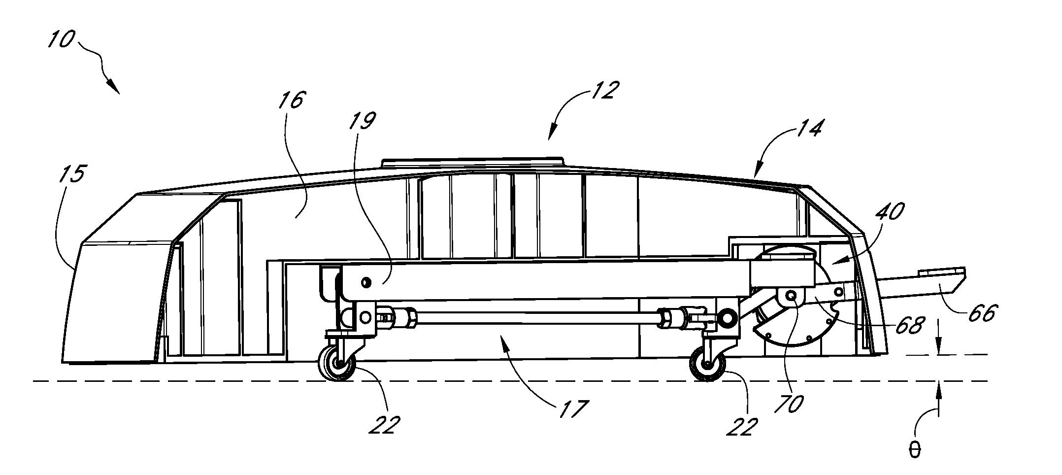
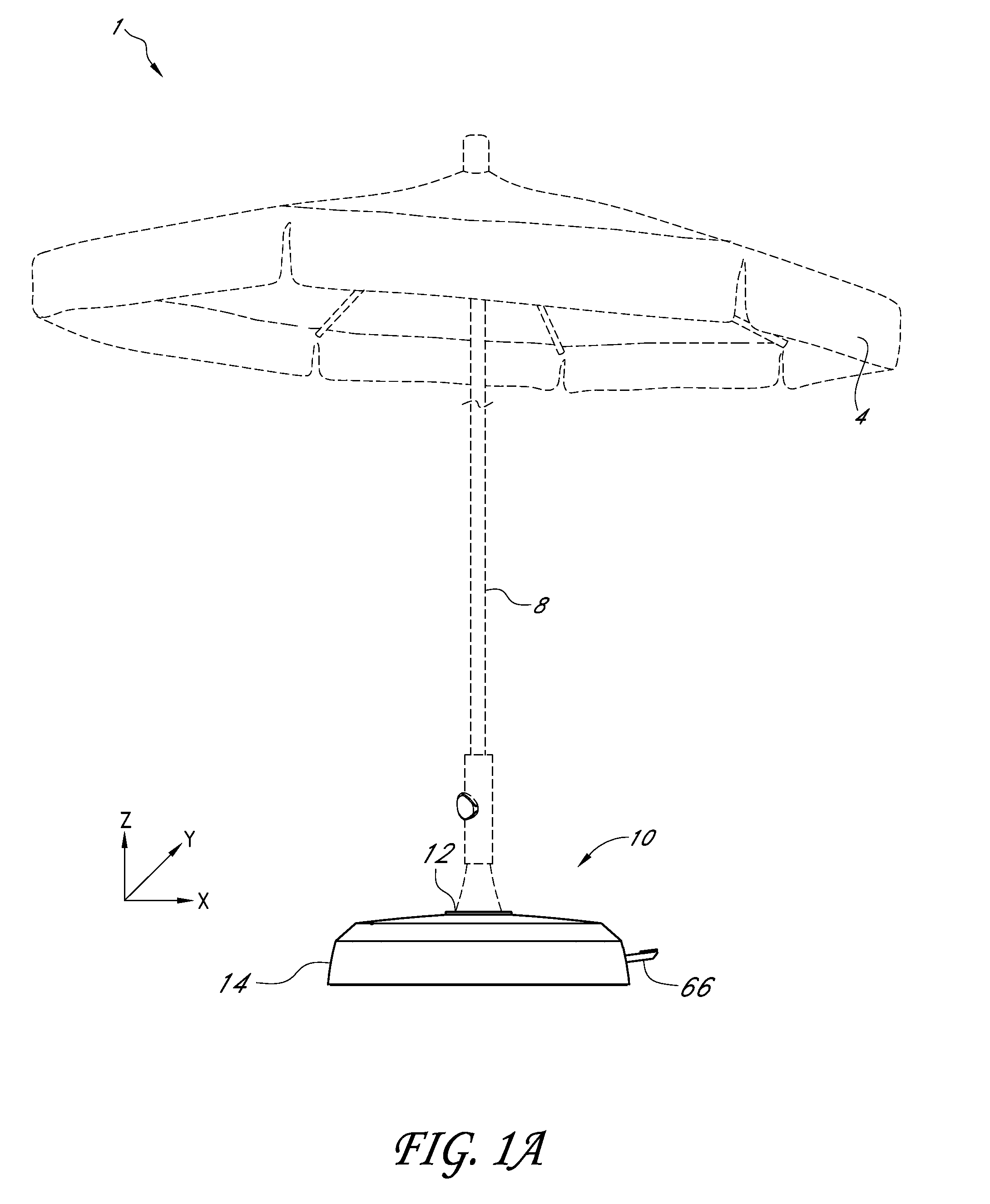
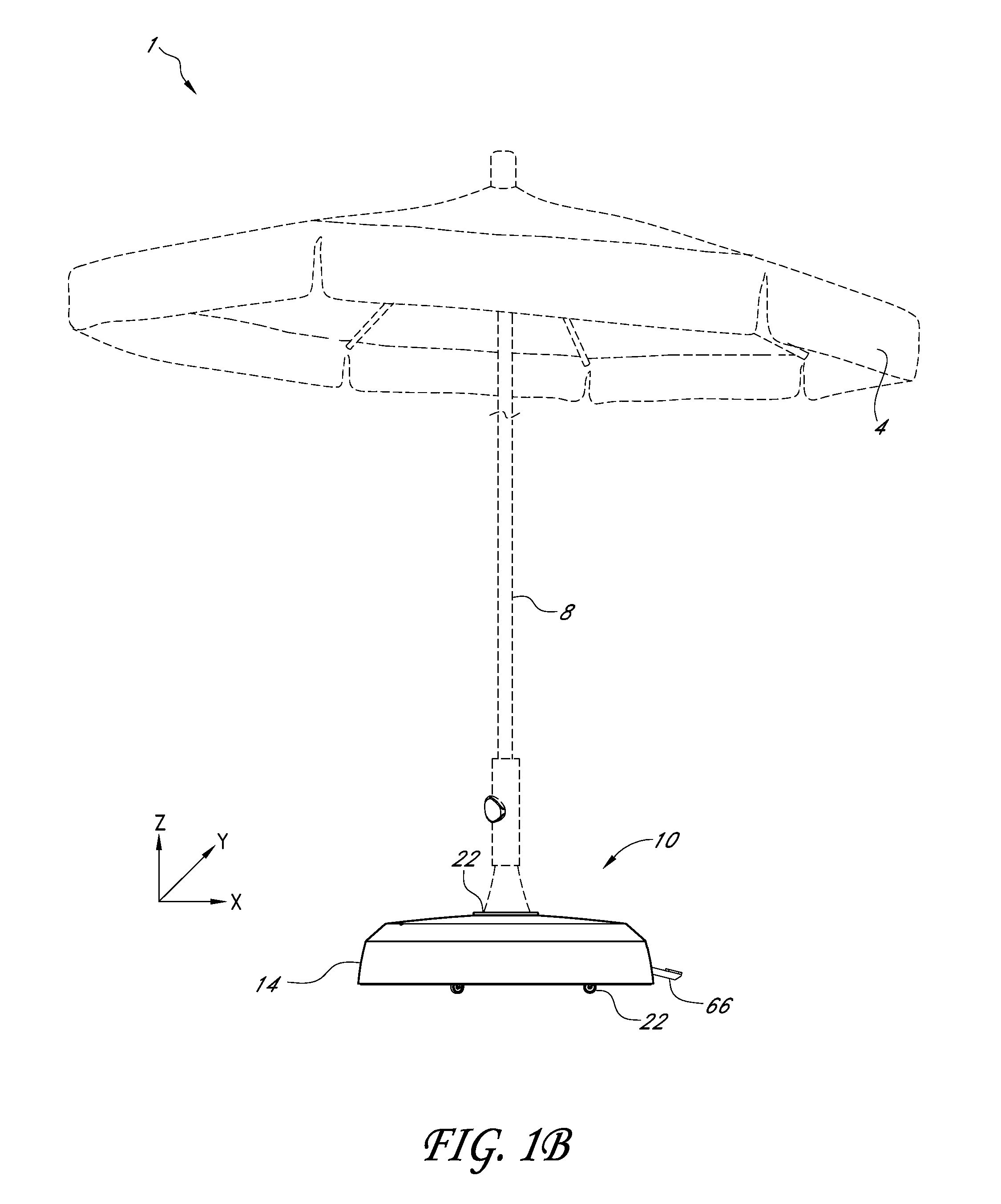
[0023]FIGS. 1A, 1B, and 4 depict an x-y-z Cartesian coordinate system, with the base assembly 10 primarily lying in the x-y plane. To assist in the description of these components, the following terms are used. As described herein, terms such as “height” refer to distance in the z-direction, and “higher / upward” and “lower / downward” refer to the positive and negative z-direction, respectively. Similarly, terms such as “lateral” will refer to the y-direction and “longitudinal” will refer to the x-direction. However, in other embodiments these axes could be rotated, reversed, or otherwise altered. Terms such as “clockwise” and “counter-clockwise” should be interpreted relative to the perspective of the figures, and it will be understood that these directions may be reversed when other perspectives are used. A detailed description of preferred embodiments of movable base assemblies and their associated methods of use now follows.

[0024]FIG. 1A illustrates one embodiment, in which an umbr...


PUM


Abstract

A ratcheting assembly can include a housing, a ratcheting gear, a first ratchet pawl, a motion translation member, and a ratcheting actuation member. The ratcheting gear can rotatably mount within the housing and include a plurality of ratchet teeth and an eccentric opening. The eccentric opening can include a rotational center of the ratcheting gear. The first ratchet pawl can mount to the housing adjacent to the ratcheting gear to allow rotation in a first direction and to hinder rotation in a second direction opposite the first direction. The motion translation member can mount within the opening such that rotation of the ratcheting gear can cause a movement of the motion translation member via rotation of the eccentric opening. The ratcheting actuation member can mount to the housing and include a second ratchet pawl. The second ratchet pawl can mount to the ratcheting actuation member adjacent to the ratcheting gear such that actuation of the ratcheting actuation member in the first direction can cause a rotation of the ratcheting gear and actuation of the ratcheting actuation member in the second direction opposite the first direction does not cause a rotation of the ratcheting gear.

Description

CROSS-REFERENCE TO RELATED APPLICATIONS[0001]This application claims the priority benefit under 35 U.S.C. §119(e) to U.S. Provisional Patent Application Ser. No. 61 / 361,322 (filed 2 Jul. 2010), the entirety of which is hereby expressly incorporated by reference herein.BACKGROUND OF THE INVENTIONS[0002]1. Field of the Inventions[0003]The inventions generally relate to load-supporting bases, and more particularly load-supporting bases with retractable wheels.[0004]2. Description of the Related Art[0005]In some cases heavy objects such as ladders and platforms are desired to be portable to enable their use in a variety of locations. For example, it is a common practice at retail stores to keep inventory in high shelves above the merchandise accessible to customers. The inventory is accessed using a portable ladder device that has wheels enabling the ladder to move about the store. A break device is sometimes provided with these ladders to immobilize the ladder when being used to access...

Claims


Application Information

Patent Timeline
Patent Type & Authority Applications(United States)
IPC IPC(8): A45B25/00F16M13/00G05G1/30B62B3/02
CPCE04H12/2238F16M7/00B62J11/00Y10T74/2133A45B25/00B62B3/02G05F1/30
Inventor MA, OLIVER JOEN-AN
Owner OLIVER JOEN AN MA
Why Eureka
Try Eureka