Method of manufacturing a watch plate

a manufacturing method and technology of a watch plate, applied in the field of manufacturing a watch plate, can solve the problems of high manufacturing cost, high manufacturing cost, and extremely complex geometry of the watch plate, and achieve the effects of saving time and money, high mechanical performance, and high mechanical performan

Active Publication Date: 2012-02-02
THE SWATCH GRP RES & DEVELONMENT LTD
View PDF0 Cites 14 Cited by
  • Summary
  • Abstract
  • Description
  • Claims
  • Application Information

AI Technical Summary

Benefits of technology

[0011]In a first embodiment, the method uses the advantageous shaping properties of amorphous materials by applying a simple forging method. In fact, these amorphous metals have the peculiar characteristic of softening while remaining amorphous within a given temperature range [Tg−Tx] particular to each alloy (Tg: the vitreous transition temperature and Tx: the crystallisation temperature). It is therefore possible to shape such metals under low stress, on the order of the megapascal (MPa), and at low temperatures that may be as low as at least 200° C. depending upon the material. This then means that fine and precise geometries can be very precisely reproduced, since the viscosity of the alloy is greatly decreased, allowing it to mould to all the details of the dies. This is typically suitable for a complex and precise part such as a watch plate.
[0013]One advantage of this embodiment is that it is simpler to achieve and does not require the use of an amorphous preform. Indeed, this method uses simple techniques for making parts by casting, thereby requiring the use of less complex tools associated with the use of the amorphous area of said material. As for the first embodiment, this then means that fine and precise geometries can be precisely reproduced, since the viscosity of the alloy is greatly decreased and the latter then moulds to all of the details of the mould. This simplification leads to a sizeable financial saving.
[0015]Another advantage follows from this capacity to match the shapes of the mould perfectly. Indeed, the plate manufacturing steps can thus be combined with the decoration steps at the same time. It is possible to envisage this solution by making the decorations straight onto the mould or dies so as to reproduce them straight away during manufacture of the plate. This again saves time and money.
[0016]Finally, the use of amorphous materials allows more resistant alloys with high mechanical performance to be employed. Thus, manufacture of the plate is no longer subject to brass machining. It is thus clear that by using materials with high mechanical performance, it also becomes possible to reduce the dimensions of said plate, particularly the thickness thereof, with the same mechanical features.

Problems solved by technology

These plates have an extremely complex geometry and have to be very precise.
However, the major drawback of this requirement for extreme precision is a very high manufacturing cost.
Manufacturing costs are further increased by adding the most prestigious surface decorations to the movements.
Of course, these aesthetic improvements require specialised machines, the cost of which is considerable.

Method used


Image

  • Method of manufacturing a watch plate
  • Method of manufacturing a watch plate

Examples


first embodiment

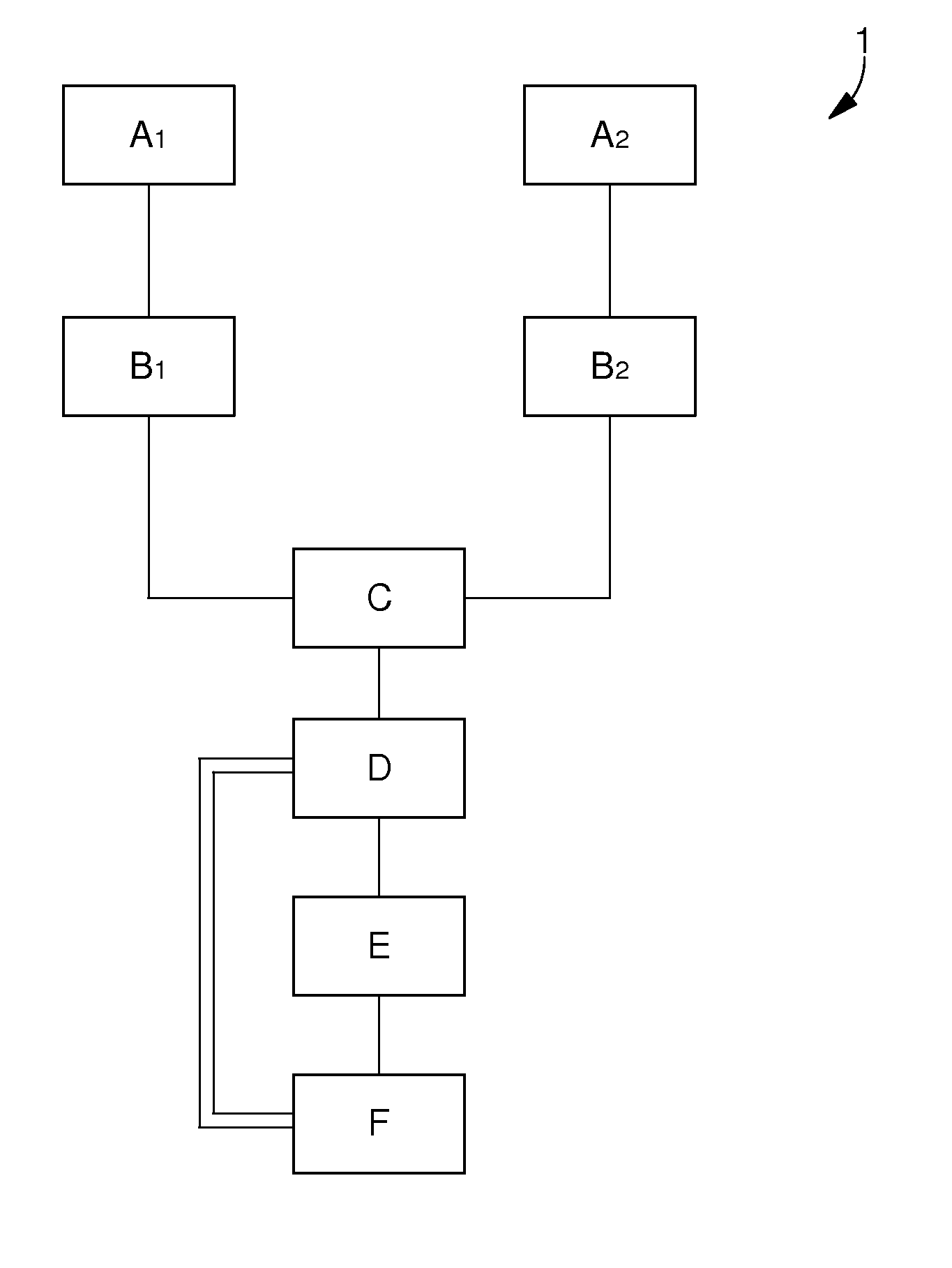
[0021]A first embodiment consists in using hot shaping via a press.

[0022]The first step A1 consists first of all in making the dies for the plate. The dies each have an inner face including the negative pattern cavity of the plate to be manufactured. The dies are provided with means for evacuating any surplus material. Of course, since manufacture of these dies does not form part of the subject of the present invention, any possible methods for making the dies may be envisaged.

[0023]Secondly, this first step A1 consists in taking the material in which the plate will be made. According to the present invention, the material used is an at least partially amorphous material. Preferably, a totally amorphous material will be used. Said material may or may not then be a precious metal. Of course, the metal could also be an alloy.

[0024]The use of amorphous material advantageously allows the dimensions to be reduced. Amorphous materials have deformation and elastic limit characteristics tha...

second embodiment

[0030] the plate is made by casting, such as, for example, pouring a liquid metal into a mould. To achieve this, step A2 consists first of all in making the mould for the plate by any possible method.

[0031]Secondly, this first step consists in taking the material in which the plate will be made. In this second embodiment, it is not essential to use an amorphous material. In fact, it does not matter whether the material is crystalline or already amorphous since the casting principle requires the material to be placed in liquid form, i.e. at a higher temperature than Tx. It is not, therefore, necessary to have a particular crystalline structure beforehand, since placing the material in a liquid state will unstructure said material.

[0032]However, since the melting temperature of amorphous metals is lower than that of crystalline metals, the method is thus easier to implement. The casting could also be by injection, allowing the liquid material to better match the shapes of the mould.

[0...


PUM

PropertyMeasurementUnit
temperaturesaaaaaaaaaa
solidification shrinkageaaaaaaaaaa

Abstract

The present invention relates to a method of making a timepiece plate. This method is characterized in that it includes the following steps:a) taking (A1, A2) the material forming the plate including at least one metallic element;b) forming (B1, B2) the plate;c) cooling (C) everything so as to obtain the timepiece plate in an at least partially amorphous state; andd) retrieving (D) the plate.

Description

[0001]The present invention concerns a method of making a timepiece element.BACKGROUND OF THE INVENTION[0002]Watch plates made of crystalline materials are known in the prior art. These watch plates are fixed inside the watch case and support numerous elements. Among the elements supported by said plate are the bridges and various members of the movement, such as the gears. These plates have an extremely complex geometry and have to be very precise. Thus, in order to make this part easy to machine, brass is generally used.[0003]However, the major drawback of this requirement for extreme precision is a very high manufacturing cost. This requires machining techniques and particularly the use of digitally controlled machining centres centres of high quality in order to satisfy the desired precision, and a very large number of steps.[0004]Manufacturing costs are further increased by adding the most prestigious surface decorations to the movements. These decorations, such as satin finish...

Claims


Application Information

Patent Timeline
Patent Type & Authority Applications(United States)
IPC IPC(8): C22F1/00
CPCG04B29/027B21J1/006C22F1/00G04B29/02B22D25/026G04B19/06
Inventor BAZIN, JEAN-LUCBOURBAN, STEWESWINKLER, YVESGRUPP, JOACHIMBREBNER-GRUPP, NATHALIE
Owner THE SWATCH GRP RES & DEVELONMENT LTD
Why Eureka
Try Eureka