Submarine electric power transmission cable armour transition

a technology of electric power transmission cable and armour, which is applied in the direction of power cables, cables, insulated conductors, etc., can solve the problems of permanent deterioration of electrical or mechanical properties of cables, magnetic field generated by current flowing in the conductor/s, friction and heat loss, etc., to avoid mechanical and electric problems and uniform mechanical and handling characteristics

Active Publication Date: 2012-02-02
PRYSMIAN SPA
View PDF9 Cites 59 Cited by
  • Summary
  • Abstract
  • Description
  • Claims
  • Application Information

AI Technical Summary

Benefits of technology

[0028]While the armour material changes from one cable section to another, the cable structure remains the same (i.e. the transition from a section to another affects the cable armour material only) thus giving the system uniformity in mechanical and handling characteristics and avoiding mechanical and electric problems associated with the connection of two conductors and to the reconstruction of the electrical insulation associated thereto. The sections of the cable of the invention substantially constitute a continuum in the cable structures such as conductor / s, insulation layers and sheathes, the transition between sections involving the armour elements only.

Problems solved by technology

The use of metal in the armour is particularly advisable in submarine cables due to the compressive forces eventually exerted thereon, which may be a problem for non-metallic armours.
If the current rating is exceeded for a length of time, the increase in temperature caused by the generated heat may damage the conductor insulation and cause permanent deterioration of electrical or mechanical properties of the cable.
In an AC power cable, the magnetic field generated by the current flowing in the conductor / s induces losses in ferromagnetic materials, such as low to medium carbon-containing steel used as armour wires.
This rotation of magnetic domains in the material causes friction and heat.
Such an induced heat, added to that produced by the conductor / s due to the current transport, can hinder the overall current carrying capacity of the cable, especially when the cable is deployed in environment with low or null heat dissipation capability.
Eddy currents cause energy to be lost in form of heat that, as already said above in connection with magnetic hysteresis loss, can hinder the overall cable current carrying capacity.
Each of the armour wire modified according to U.S. Pat. No. 3,925,598 still suffers from magnetic hysteresis and eddy current losses.
A corrosion problem is solved, but the magnetic hysteresis losses are still present, due to the presence of a steel core of the standard type.
The overall cost of the cable is increased.
The Applicant observes that although the problem of avoiding a reduction in the electrical power transport capability of an electric cable due to heat generated by losses in the cable armour might be solved by increasing the size of the cable, or of portions thereof, particularly of those cable sections which, in use, lay in the above-mentioned unfavourable conditions, such a solution is not satisfactory since it implies heavier and more expensive cables in the first case, or the installation of transition joints between cable sections of different cable sizes in the latter case.
Also, having a cable made up of distinct sections of different size is not desirable, because the cable continuity is impaired which is detrimental for the cable mechanical resistance and thus requires careful handling during laying operation.

Method used


Image

  • Submarine electric power transmission cable armour transition
  • Submarine electric power transmission cable armour transition
  • Submarine electric power transmission cable armour transition

Examples


Embodiment Construction

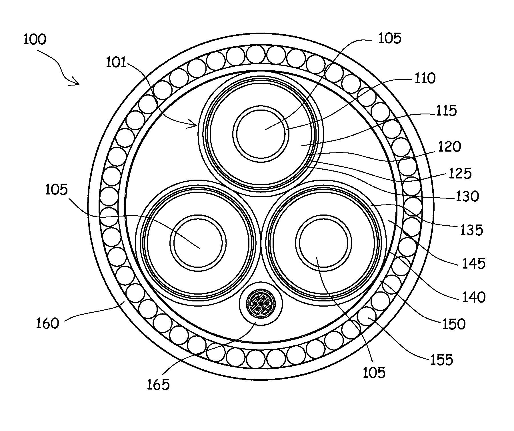
[0056]Making reference to the drawings, in FIG. 1 there is schematically shown a cross-sectional view of an electrical cable 100, particularly a submarine cable for AC electrical power transmission in the MV or HV ranges.

[0057]The cable 100 is a multi-core cable adapted to 3-phases power transmission; the number of cores 101 in the cable is not a limitation for the present invention. Preferably, the invention applies to multi-core cables with any number of cores 101, but can advantageously be applied to a single core cable, too.

[0058]In the structure shown by FIG. 1, the cable 100 is a multi-core cable comprising three cores 101, each comprising a conductor 105, surrounded by a conductor screen 110, an insulation typically comprising an insulating layer 115 and an insulation screen 120, a water barrier layer 125, a metallic screen 130 and, optionally a polymeric sheath 135.

[0059]The insulating layer 115 may be an extruded insulating layer, for example made of cross-linked polyethyle...


PUM

PropertyMeasurementUnit
lengthaaaaaaaaaa
lengthaaaaaaaaaa
temperatureaaaaaaaaaa

Abstract

An electric power transmission cable includes at least one first section provided with cable armour made of a first metallic material, and at least one second section provided with a cable armour made of a second metallic material, wherein the second metallic material has ferromagnetic properties substantially lower than those of the first metallic material.

Description

BACKGROUND OF THE INVENTION[0001]1. Field of the Invention[0002]The present invention generally relates to the field of electric cables, i.e. cables for electric power transmission, in particular, alternate current (AC) power transmission, more particularly to submarine electric cables substantially intended to be deployed underwater.[0003]2. Description of the Related Art[0004]A typical submarine cable for AC power transmission in the medium voltage (MV) and high voltage (HV) ranges (less than approximately 50 KV for MV, higher than 50 KV for HV) comprises one or more conductors (one conductor for single-phase power transmission, three conductors for 3-phases power transmission; cables with more than one conductor are also referred to as “multi-core” cables). Each conductor is surrounded by a conductor screen, an insulation structure typically comprising an insulation layer and an insulation screen, a water barrier layer, a metallic screen or sheath, and optionally a plastic sheath...

Claims


Application Information

Patent Timeline
Patent Type & Authority Applications(United States)
IPC IPC(8): H01B7/20
CPCH01B7/225H01B7/14H02G1/10H01B7/22
Inventor ORINI, AMBROGIO
Owner PRYSMIAN SPA
Why Eureka
Try Eureka