Method and apparatus for the thermal treatment of a workpiece by means of a laser beam

a technology of laser beam and thermal treatment, which is applied in the direction of laser beam welding apparatus, mechanical apparatus, manufacturing tools, etc., can solve the problems of reducing the absorbed laser power, deteriorating process efficiency, and not being freely adjustable, so as to increase the maintenance requirements of the apparatus, material and design adjustment.

Inactive Publication Date: 2012-02-02
MESSER CUTTING SYST
View PDF19 Cites 14 Cited by
  • Summary
  • Abstract
  • Description
  • Claims
  • Application Information

AI Technical Summary

Benefits of technology

[0021]With the number of the optical components for implementing the inclination of the collimated laser beam, the efforts in terms of material, design and adjustment are increasing. Dimensional deviations, adjusting errors, scattering and absorption of the laser radiation in the components and on surfaces lead to transmission losses and thus at the same time to a heating of the components. This heating just like gradual damage to the optical components by high-energy laser radiation and soiling of the surfaces during operation can again lead to a deterioration of the imaging properties and to further transmission losses and to increased maintenance requirements of the apparatus.
[0022]It is therefore desirable to configure the inclination angle of the collimated laser beam to the vertical with a very small number of optical components if possible.
[0023]It is therefore the object of the present invention to indicate a method for the thermal treatment of workpieces with laser radiation that provides a high degree of absorption for the laser radiation while making small demands on equipment and maintenance and that is distinguished by a low susceptibility to failure.

Problems solved by technology

It is however not freely adjustable.
Especially when laser beam sources of a short wavelength (e.g. of around 1 μm) are used, an inclination angle φc of the cutting front that is not optimal may be obtained, which leads to a reduction of the absorbed laser power and thus to a deterioration of the process efficiency.
If this beam formation is carried out by using baffles or masks, a part of the radiation power is cut off and is not available for the cutting process.
Lasers with a rectangular or oval beam cross-section are difficult to produce and expensive.
Such devices for laser beam angle cutting are e.g. used for fiber cutting and are designed for large tilt angles and are thus large and expensive.
The problem arises here that the media supply lines as well as the drive for adjusting the bevel angle must be rotatable by more than + / −360°.
Rotary feedthroughs for gases or electric current are however prone to failure and expensive: A separate drive which must be co-rotated is needed for tilting the laser head, which makes the unit heavy and less dynamic on the whole.
Fogging and soiling of the optical reflection surfaces cannot be avoided completely under the rough work conditions prevailing in practice.
Moreover, the assembly requires a certain height of the free space above the treatment plane that is however often not available.
Dimensional deviations, adjusting errors, scattering and absorption of the laser radiation in the components and on surfaces lead to transmission losses and thus at the same time to a heating of the components.
This heating just like gradual damage to the optical components by high-energy laser radiation and soiling of the surfaces during operation can again lead to a deterioration of the imaging properties and to further transmission losses and to increased maintenance requirements of the apparatus.

Method used


Image

  • Method and apparatus for the thermal treatment of a workpiece by means of a laser beam
  • Method and apparatus for the thermal treatment of a workpiece by means of a laser beam
  • Method and apparatus for the thermal treatment of a workpiece by means of a laser beam

Examples


embodiment

[0066]The invention will now be explained in more detail with reference to embodiments and a drawing. Schematically shown is in detail in:

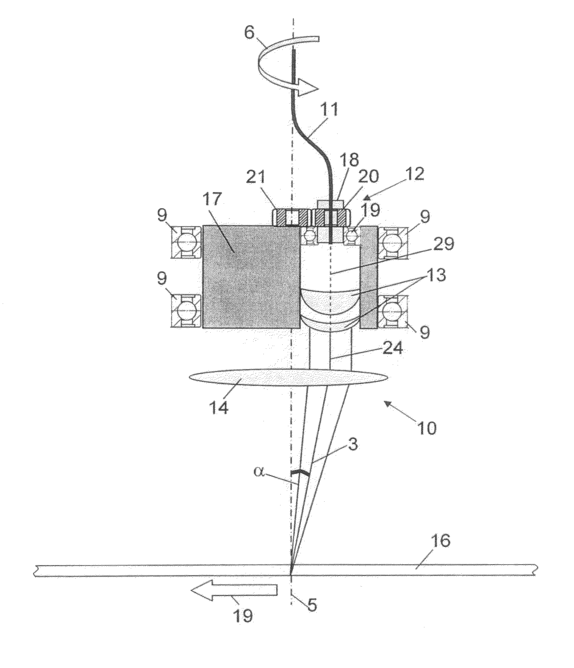
[0067]FIG. 1 a first embodiment of an optical system for guiding and forming a laser beam for use in a laser head according to the invention in a side view (without housing of the laser head);

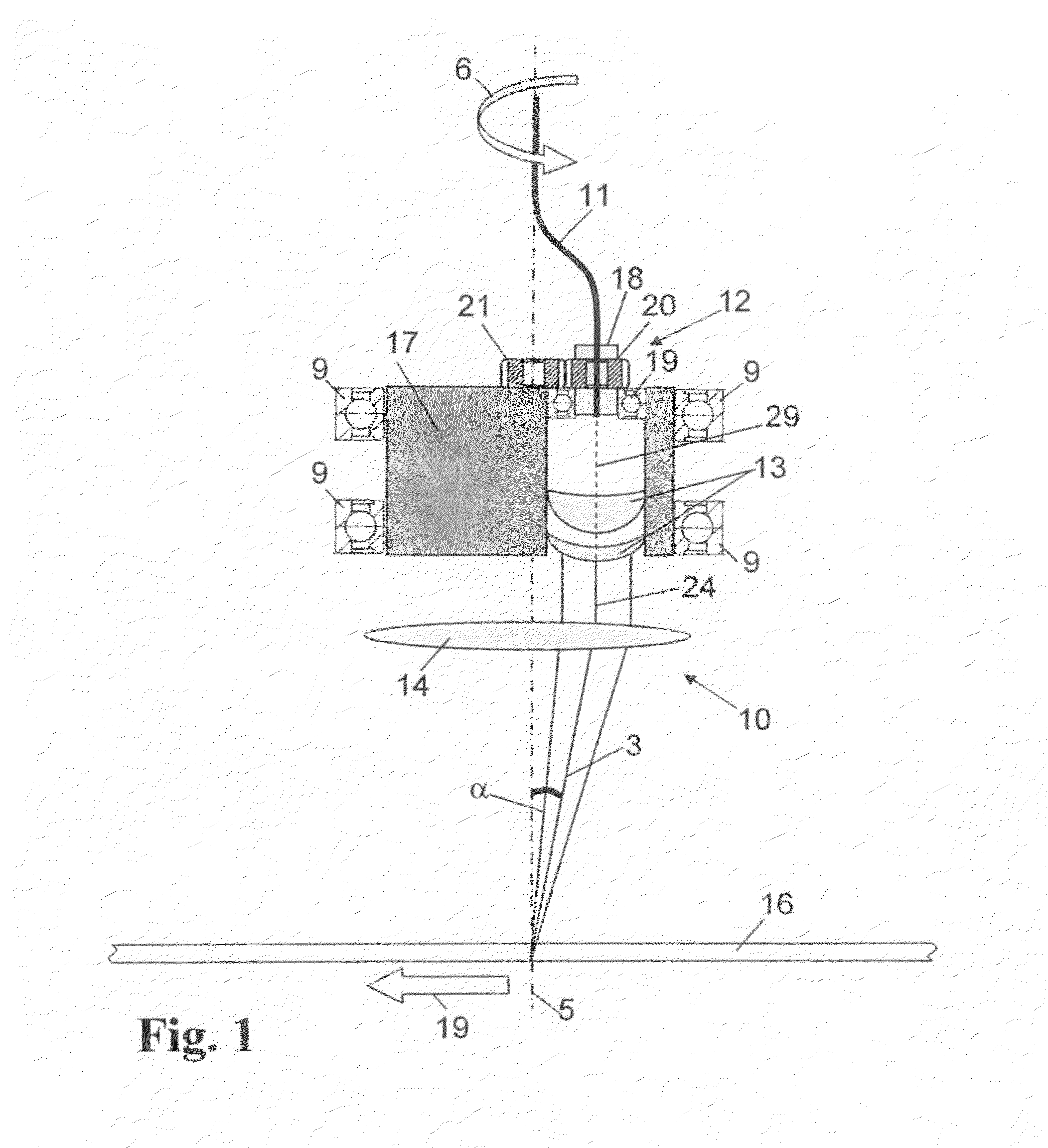
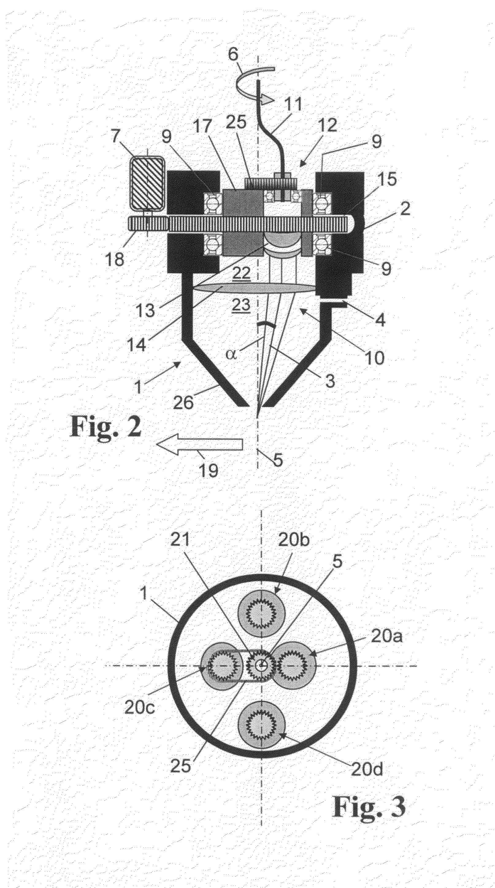
[0068]FIG. 2 the optical system of FIG. 1 with laser head housing;

[0069]FIG. 3 the laser head of FIG. 1 in a top view from above;

[0070]FIG. 4 a second embodiment of an optical system for guiding and forming a laser beam for use in a laser head according to the invention in a side view (without laser head);

[0071]FIG. 5 the optical system of FIG. 4 with laser head housing; and

[0072]FIG. 6 the system for guiding and forming the laser beam of FIG. 4 in a top view.

[0073]FIG. 2 shows a laser head 1 with a housing 2 and a nozzle 26 through which a cutting gas and a laser beam 3 exit, the laser beam 3 being inclined and focused relative to the vertical. The housing 2...


PUM

PropertyMeasurementUnit
tilt angleaaaaaaaaaa
bevel angleaaaaaaaaaa
angleaaaaaaaaaa

Abstract

In the thermal cutting of a workpiece by means of a laser beam, said beam is generated by means of a laser source and supplied to a movable laser head. In the laser head, an optical deflection element is provided for deflecting the laser beam such that, when viewed in working direction, it encloses a tilt angle (α) differing from 0 degrees with the longitudinal axis of the laser head. Starting therefrom, to produce the inclination of the collimated laser beam to the vertical with a very small number of optical components if possible, the invention suggests that the laser beam is supplied to the laser head by means of an optical fiber and the laser beam is collimated, passes through the deflection element laterally offset to the longitudinal axis of the laser head and is deflected by means of said element onto the workpiece surface and focused at the same time.

Description

[0001]The invention relates to a method for the thermal treatment, particularly for the thermal cutting, of a workpiece with a laser beam which is generated by means of a laser source, said laser beam is supplied to a laser head having a longitudinal axis and being movable relative to the surface of the workpiece in a working direction, said laser beam exits via a nozzle towards the workpiece, at least one optical deflection element being provided in the laser head for deflecting the laser beam such that, when viewed in working direction, it encloses a tilt angle α differing from 0 degrees with the surface normal to the workpiece surface.[0002]Furthermore, the present invention relates to an apparatus for the thermal treatment of a workpiece with a laser beam, particularly for thermal cutting, comprising a laser source for generating the laser beam, a laser head which has a longitudinal axis and which is made movable relative to the surface of the workpiece in working direction, and...

Claims


Application Information

Patent Timeline
Patent Type & Authority Applications(United States)
IPC IPC(8): B23K26/06B23K26/02
CPCB23K26/38B23K26/046B23K26/0643B23K26/0648B23K26/0665Y10T74/19679
Inventor ECK, KARL
Owner MESSER CUTTING SYST
Why Eureka
Try Eureka