
Water resistant surface mount device package

a technology of device packaging and surface mount, applied in the field of electromechanical packaging, can solve the problems of reducing the overall life of the package, affecting the integrity of such packages, and deformation of the package structure during the reflow process, so as to achieve the effect of improving structural integrity and suitable surface area

Active Publication Date: 2012-02-02
CREELED INC
View PDF5 Cites 68 Cited by
  • Summary
  • Abstract
  • Description
  • Claims
  • Application Information

AI Technical Summary

Benefits of technology

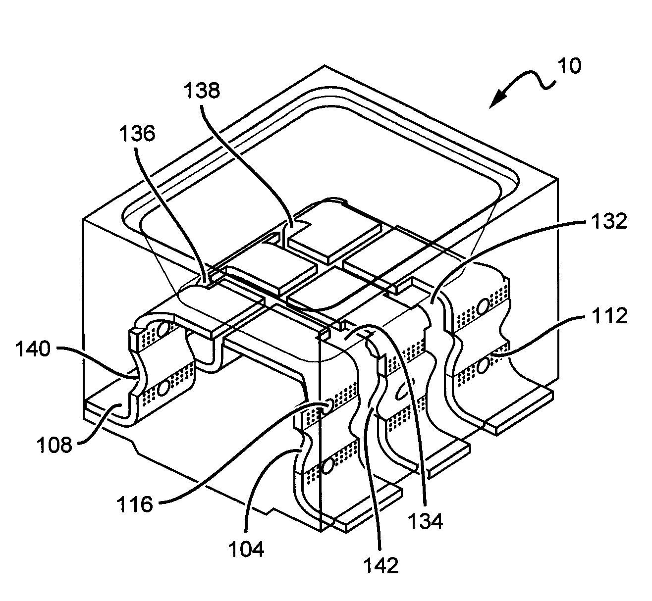
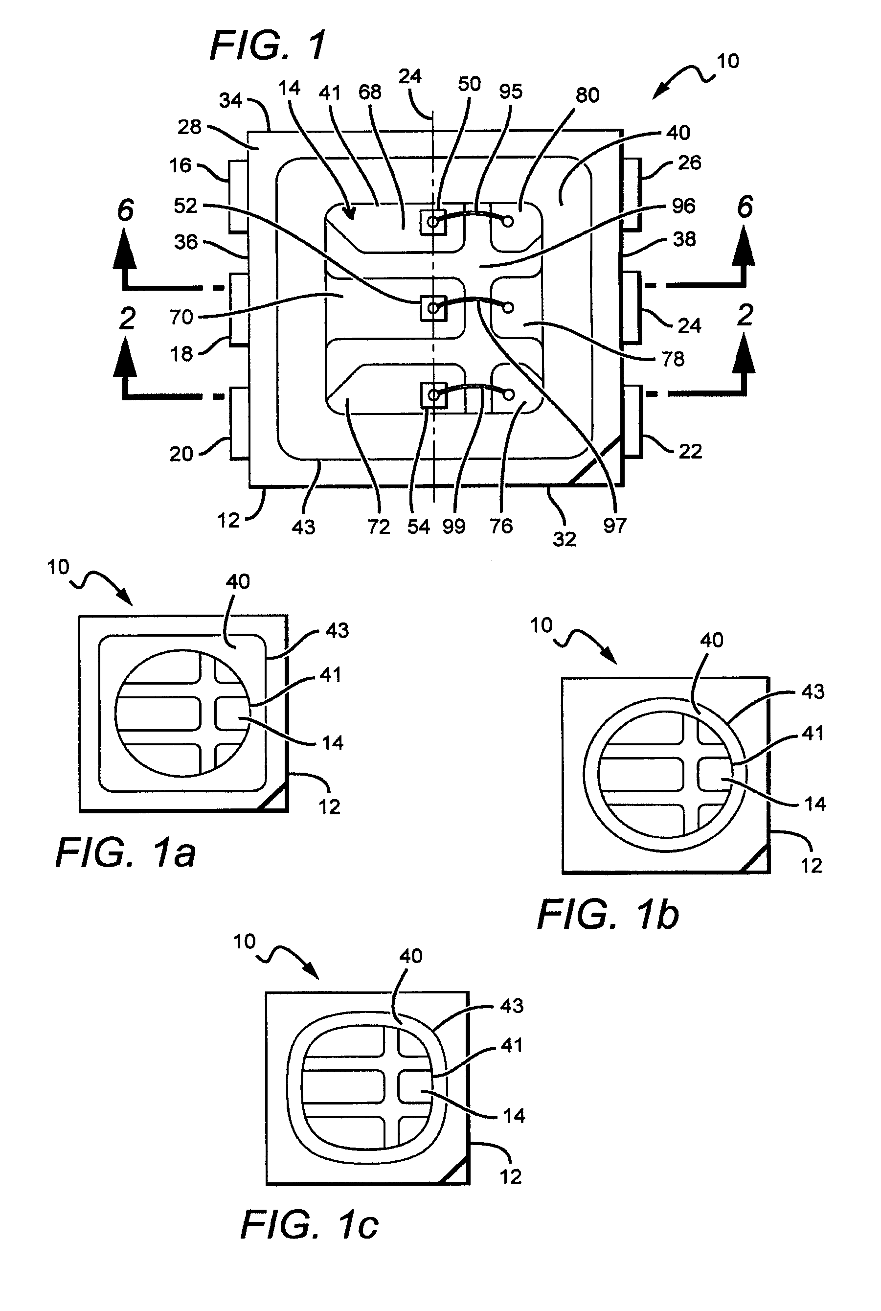
[0011]The present invention provides emitter packages and LED displays optimized for outdoor use, with the emitter packages being water resistant to withstand adverse environmental conditions. The emitter packages of the present invention have improved structural integrity, with the packages having suitable surface area for mounting a desired number of LED chips and corresponding components. Moreover, the present invention provides customizable emitter packages, which may allow for attachment to standardized mechanical / electrical supports.
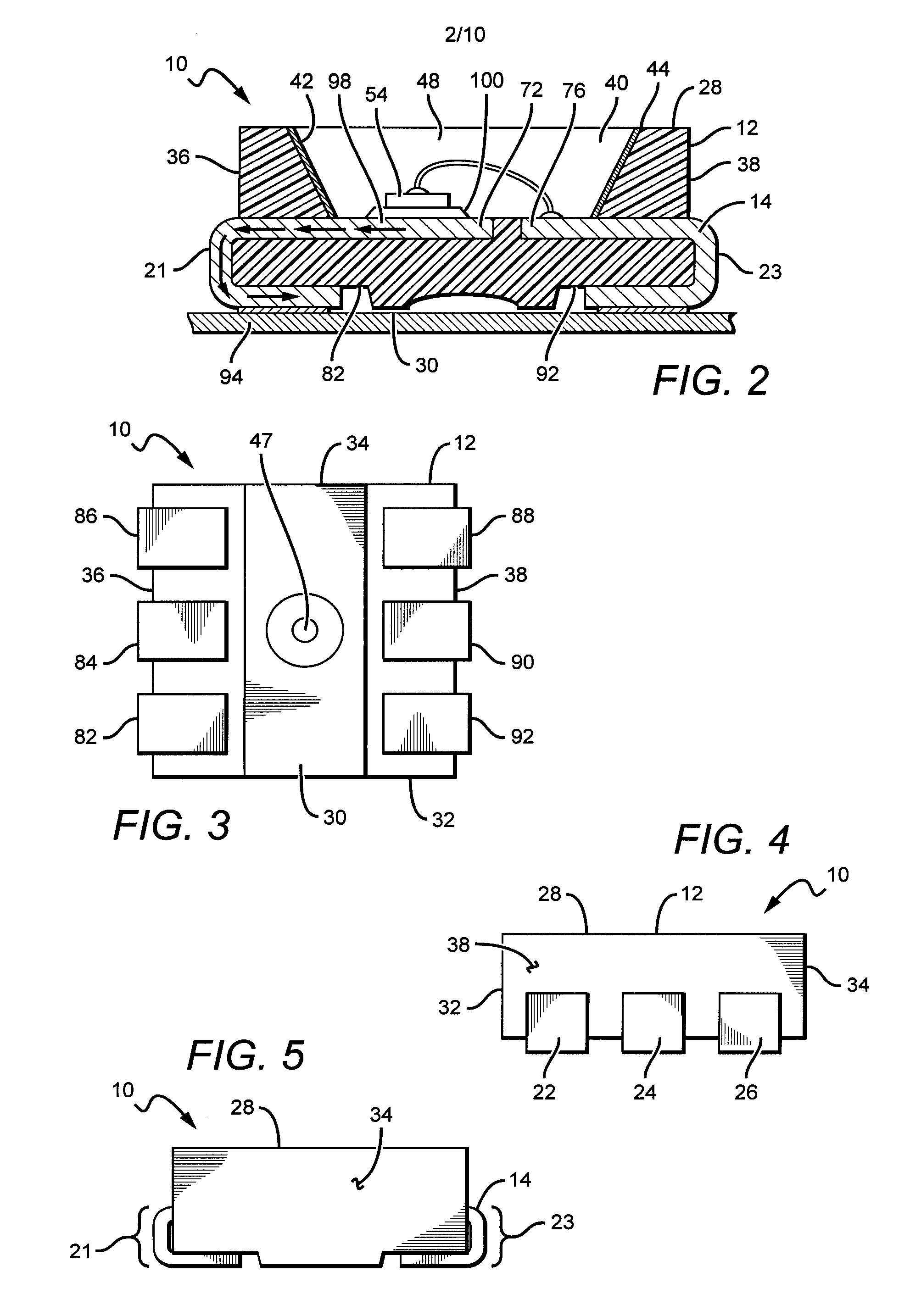
[0012]One embodiment comprises an emitter package, with the package comprising a casing with a cavity extending into the interior of the casing from a top surface of the casing, an electrically conductive lead frame integral to the casing, and a plurality of light emitting devices arranged on conductive parts of the lead frame. The lead frame comprises features to enhance adhesion between the casing and the lead frame, with the material of the casing encompassing each of the features. The light emitting devices and portions of the lead frame are exposed through the cavity. The lead frame features enable the package to be substantially water resistant.
[0013]Pursuant to another embodiment, an emitter package is provided comprising a casing with a cavity extending into the interior of the casing from a top surface of the casing, an electrically conductive lead frame integral to the casing, and a plurality of light emitting devices arranged on portions of the lead frame exposed through the cavity. The lead frame comprises features to enhance adhesion between the casing and the lead frame. The lead frame also comprises a plurality of solder pins that each extend out at least one end surface of the casing and wrap around the bottom of the casing, with the length of the solder pins being less than the overall height of the package. The lead frame features enable the package to be substantially water resistant.
[0014]In accordance with yet another embodiment, an emitter package is provided comprising a casing with a cavity extending into the interior of the casing from a top surface of the casing, a lead frame integral to the casing, a plurality of light emitting devices arranged on a portion of the lead frame exposed through the cavity, and an encapsulant over the package and in the cavity. The lead frame comprises lead frame features enhancing the adhesion between the casing and the lead frame, with the casing material encompassing the lead frame features. The cavity comprises cavity features to enhance adhesion between the encapsulant and the cavity. The lead frame features and the cavity features enable the package to be substantially water resistant.
[0015]In yet another embodiment according to the present invention, a light emitting device display is provided, comprising a substrate carrying an array of emitter packages, and electrically connected drive circuitry to selectively energize the array for producing visual images on the display. Each of the emitter packages comprises a casing with a cavity extending into the interior of the casing from a top surface of the casing, a lead frame integral to the casing, and a plurality of LEDs arranged on the lead frame, with the LEDs and portions of the lead frame exposed through the cavity. The lead frame comprises features to enhance adhesion between the casing and the lead frame, with the features enabling each of the packages to be substantially water resistant.

Problems solved by technology

The packages are expected to be robust and maintain their structural integrity during manufacture and use, but the integrity of such packages can become compromised.
Such separation can allow environmental contaminants such as water and dirt to enter the package, and can reduce the overall life of the package.
Furthermore, the package structures can become deformed during the reflow process.

Method used


Image

  • Water resistant surface mount device package
  • Water resistant surface mount device package
  • Water resistant surface mount device package

Examples


Embodiment Construction

[0045]The present invention is described herein with reference to certain embodiments, but it is understood that the invention can be embodied in many different forms and should not be construed as limited to the embodiments set forth herein.

[0046]In some embodiments according to the present invention, structures are provided for water resistant, multiple emitter packages that allow the packages to emit light in various environmental conditions by having improved package integrity. In some embodiments, the improved package integrity can be provided by having lead frames with different shapes. In other embodiments the improved package integrity can be provided by a lead frame with one or more features that improve the adhesion between the lead frame and the package casing. In still other embodiments, the different shapes can be combined with different lead frame features.

[0047]Many different lead frame features can be used and can comprise water retention features, or features that r...


PUM


Abstract

The present invention is directed to LED packages and LED displays utilizing water resistant packages with improved structural integrity and customizable attributes. In some embodiments, the improved structural integrity is provided by various features in the lead frame that the casing material encompasses to improve the adhesion between the lead frame and the casing for a stronger, water resistant package. Moreover, in some embodiments the improved structural integrity and water resistance is further provided by cavity features that improve adhesion between the cavity and a protective encapsulant. Some embodiments also provide for packages with a greater overall height than the length of their side-exposed solder pins, which improves gel coverage of the side-exposed solder pins between adjacent packages.

Description

[0001]This application claims the benefit of U.S. Provisional Patent Application Ser. No. 61 / 369,565, filed on Jul. 30, 2010.BACKGROUND OF THE INVENTION[0002]1. Field of the Invention[0003]The present invention relates generally to electronic packaging, and more particularly to water resistant surface mount packaging having multiple emitters for outdoor displays.[0004]2. Description of the Related Art[0005]Light emitting diodes (LEDs) are solid state devices that convert electric energy to light, and generally comprise one or more active layers of semiconductor material sandwiched between oppositely doped layers. When a bias is applied across the doped layers, holes and electrons are injected into the active layer where they recombine to generate light. Light is emitted from the active layer and from all surfaces of the LED.[0006]In recent years, there have been dramatic improvements in LED technology such that LEDs with increased brightness and color fidelity, smaller footprints, a...

Claims


Application Information

Patent Timeline
Patent Type & Authority Applications(United States)
IPC IPC(8): H01L33/62
CPCH01L25/0753H01L33/486H01L33/62H01L2224/48091H01L2224/48465H01L2224/73265H01L2224/32245H01L2933/0033H01L2924/09701H01L2224/48247H01L2924/1815H01L2924/00014H01L2924/00H01L2924/00012H01L24/73
Inventor CHAN, ALEX CHI KEUNGPANG, CHARLES CHAK HAU
Owner CREELED INC
Learn More