Hand Cart Braking System

Active Publication Date: 2012-02-02
WYSE GENE +1
View PDF6 Cites 3 Cited by
  • Summary
  • Abstract
  • Description
  • Claims
  • Application Information

AI Technical Summary

Benefits of technology

[0029]An additional object of the present invention is to provide a braking system which can be mounted on existing hand carts. The axle and wheel moun

Problems solved by technology

A significant problem which occurs during use of a hand cart is controlling a loaded hand cart on an inclined surface.
The inability to control a loaded hand cart on an inclined surface frequently results in damage to the load being moved and injury to the pers

Method used


Image

  • Hand Cart Braking System
  • Hand Cart Braking System
  • Hand Cart Braking System

Examples


Embodiment Construction

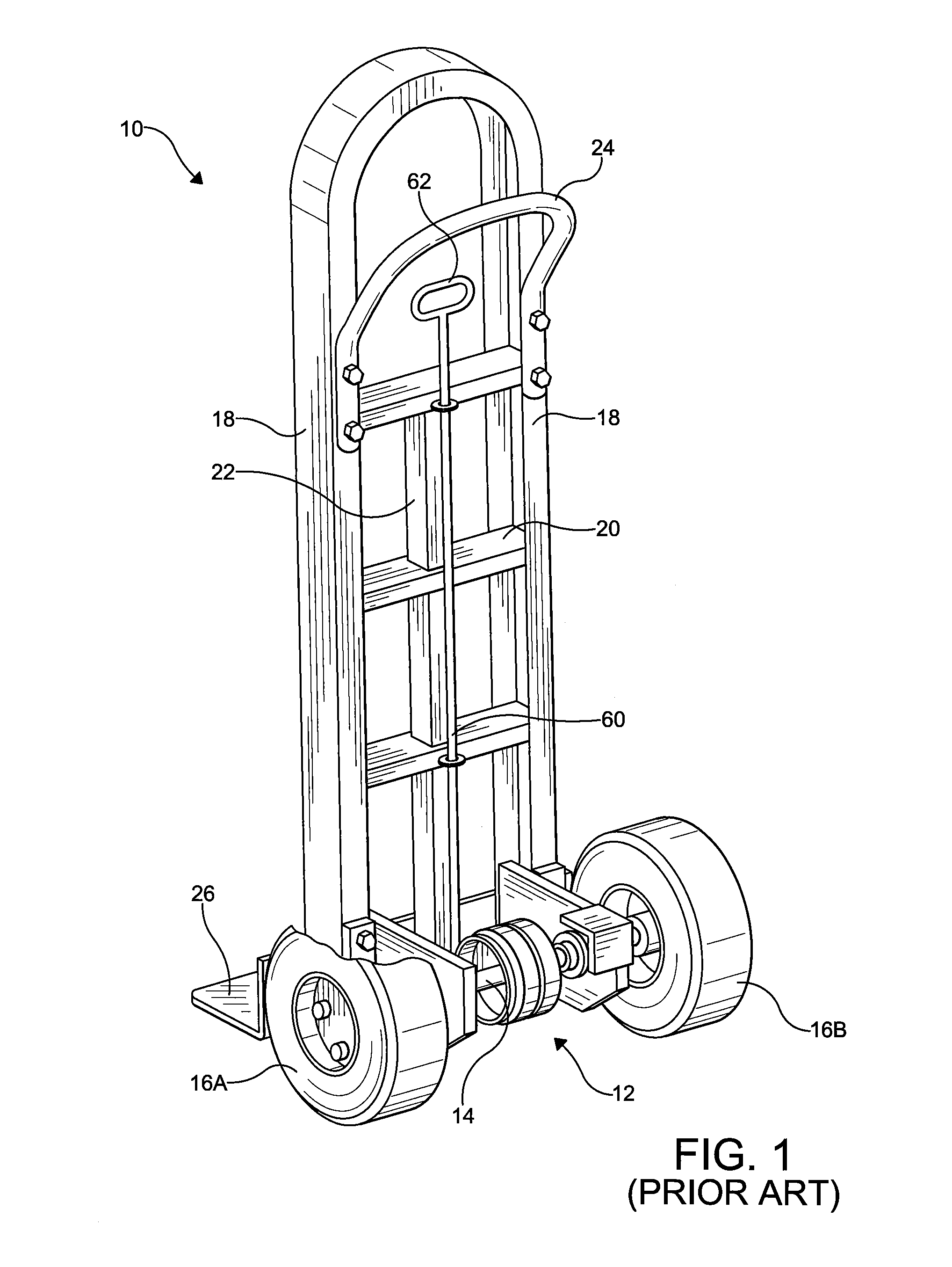
[0033]FIG. 1 shows a known hand cart with a brake system as known in the art. The braking system of the present invention is suitable for use in such a cart as is disclosed herein.

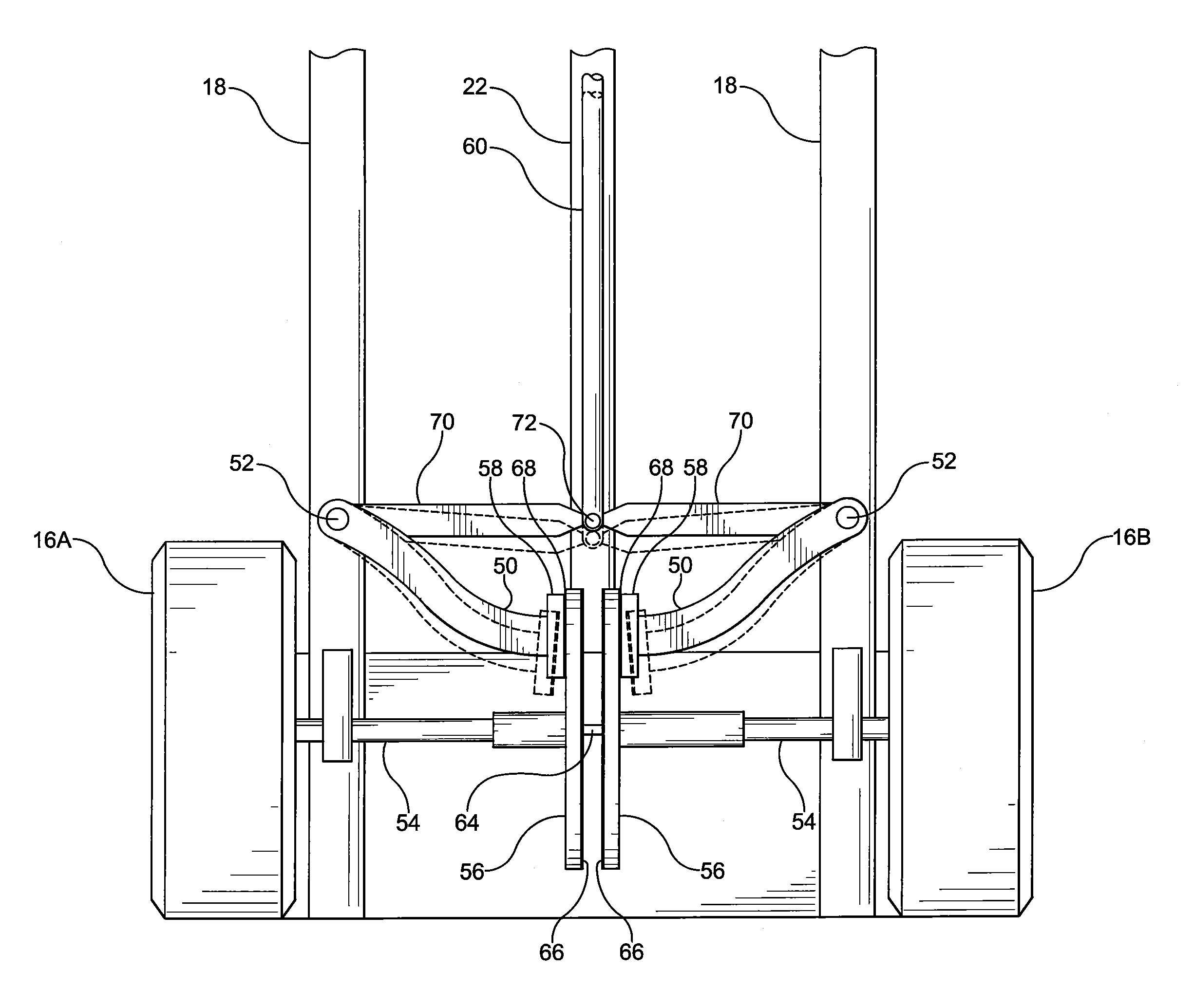
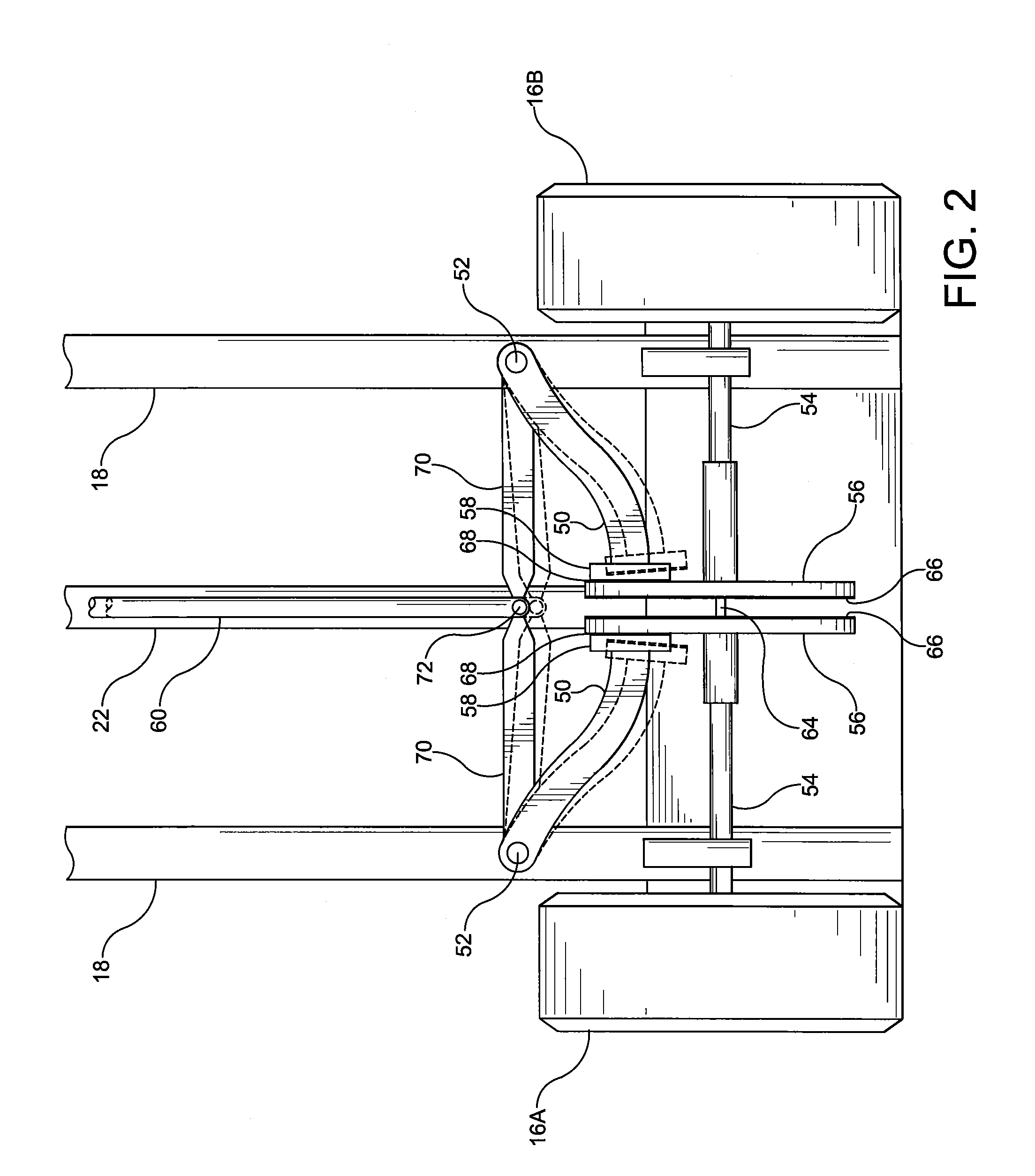
[0034]In FIG. 1, a known hand cart 10, which is suitable for use with the present invention, includes a braking system 12 mounted on the split axle 14 extending between the wheels 16a, 16b of the hand cart 10. The hand cart 10 is formed by two elongated, parallel load supporting frame members 18 with cross members 20 and center strut 22. A curved handle 24 is formed at the upper end of the frame members 18. Various handle configurations are known in the industry to facilitate operation of the hand cart 10. The frame members 18 and cross members 20 are typically made from steel or aluminum tubing or bars. An actuator bar 60 with a handle 62 is used to activate the brake system 12.

[0035]At the front, lower end of the frame members 18, a lifting blade 26 is mounted to extend perpendicularly from the frame mem...


PUM


Abstract

An improved braking system for a hand cart is disclosed. The braking system has a split axle which is rotatably connected to the cart frame. Braking components are affixed to each of the split axle sections. An actuator is connected to a caliper system, which caliper system is used to push the braking components together to lock the split axle into a single axle for braking or controlling the cart.

Description

RELATED APPLICATIONS[0001]This application claims the benefit of provisional application U.S. 61 / 369,037, filed Jul. 29, 2010. U.S. 61 / 369,037 was pending as of the filing date of the present application.BACKGROUND OF THE INVENTION[0002]1. Field of the Invention[0003]The present invention relates to a hand operated braking system for a hand cart. More particularly, the present invention includes a hand cart braking system with a single clutch braking system.[0004]2. Summary of Related Art[0005]Hand carts are well known in the material handling industry for loading and unloading material from trucks and trailers. Hands carts are used not only at truck loading docks, but also at retail establishments and other delivery points. Hand carts are also essential devices for moving loads within warehouses and production facilities. The primary construction of a hand cart includes two wheels on a single axle, two vertical frame members with cross frame members, a handle at the top of the fram...

Claims


Application Information

Patent Timeline
IPC IPC(8): B62B5/04B62B1/10
CPCB62B5/0438B62B2005/0471B62B5/048
Inventor WYSE, GENEWYSE, RANDY
Owner WYSE GENE
Why Eureka
Try Eureka