Drive controller

a technology of drive controller and drive controller, which is applied in the direction of electric variable regulation, process and machine control, instruments, etc., can solve the problem of difficult to obtain the desired reverse recovery characteristics

Active Publication Date: 2012-02-02
DENSO CORP
View PDF8 Cites 37 Cited by
  • Summary
  • Abstract
  • Description
  • Claims
  • Application Information

AI Technical Summary

Benefits of technology

[0009]According to an aspect of the present invention, a drive controller for driving an inductive load connected to a node between a first switching device and a second switching device that are connected in series with a direct current voltage source includes a first diode, a series circuit of a second diode and an inductor, and a control circuit. The first diode is connected in antiparallel with the first switching device and a parasitic diode of the first switching device. The series circuit is connected in ...

Problems solved by technology

It may be difficult to obtain desired reverse recovery characteristics before and after turn-ON of...

Method used


Image

  • Drive controller
  • Drive controller
  • Drive controller

Examples


first embodiment

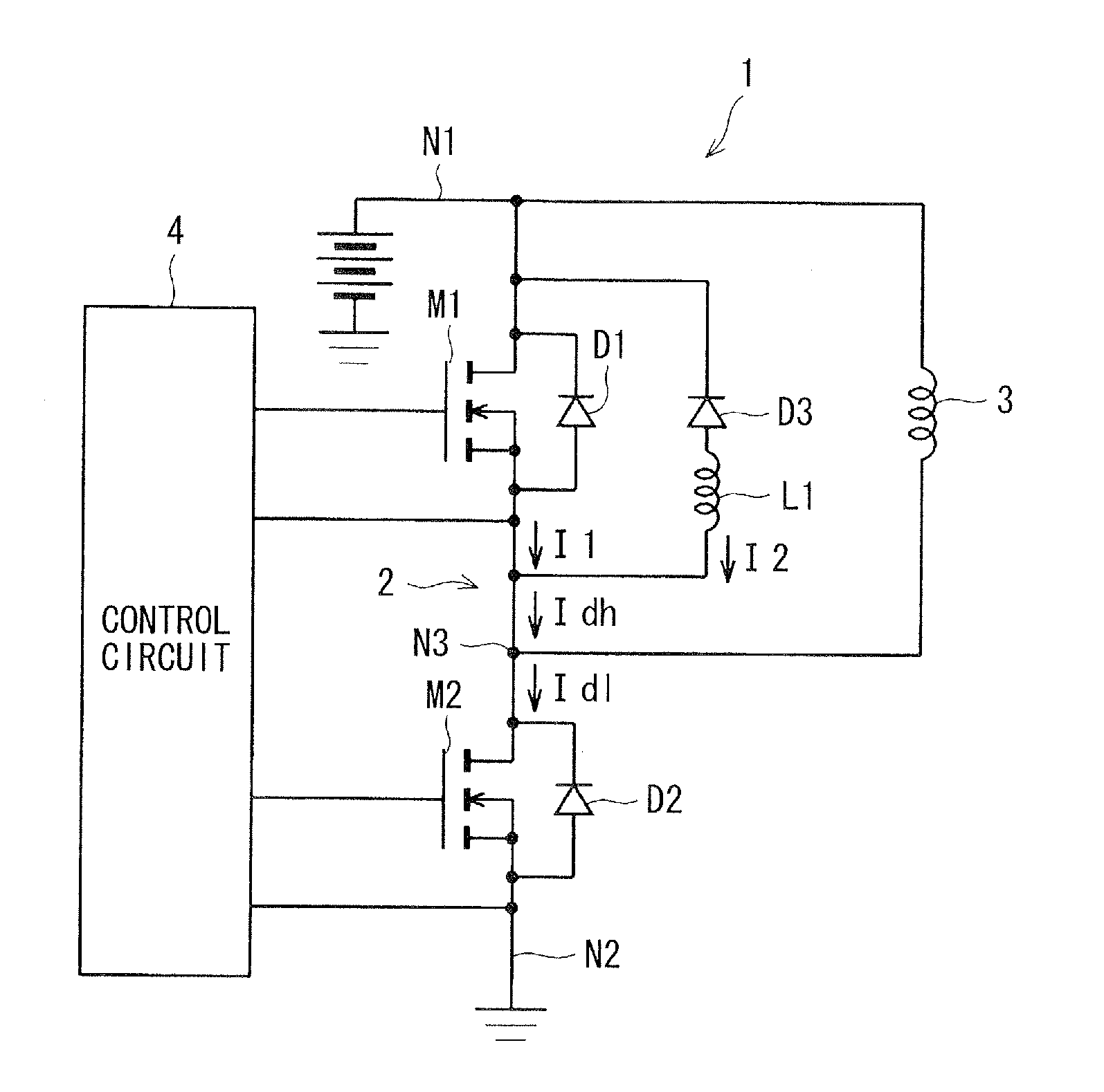
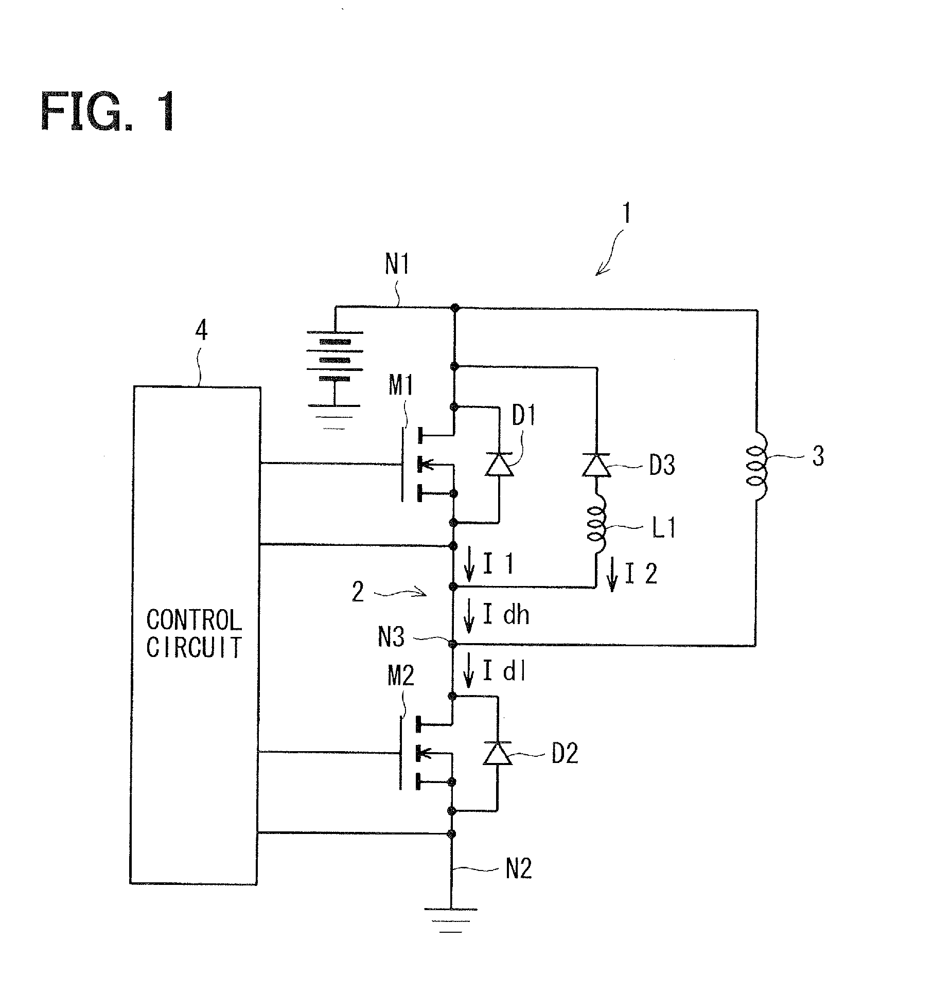
[0029]A drive controller 1 according to a first embodiment of the present invention is described below with reference to FIGS. 1-11B. As shown in FIG. 1, the drive controller 1 includes a high-side N-channel MOSFET Mi and a low-side N-channel MOSFET M2. The MOSFET M1 and the MOSFET M2 are connected in series to form a half-bridge circuit 2 between positive and negative terminals N1 and N2 of a direct-current (DC) power source. The half-bridge circuit 2 drives an inductive load 3 that is connected to a node N3 between the MOSFET M1 and the MOSFET M2.

[0030]The drive controller 1 further includes a control circuit 4. The control circuit 4 drives the gates (i.e., control terminals) of the MOSFETs M1 and M2. The MOSFET M1 has an intrinsic antiparallel body diode (i.e., parasitic diode) D1 that is connected between the drain and the source to conduct a circulating current.

[0031]Likewise, the MOSFET M2 has an intrinsic antiparallel body diode (i.e., parasitic diode) D2 that is connected be...

second embodiment

[0072]A drive controller 1 according to a second embodiment of the present invention is described below with reference to FIGS. 15 and 16A-16C. A difference between the first embodiment and the second embodiment is as follows.

[0073]The second embodiment is similar to the modification of the first embodiment. According to the modification of the first embodiment, the control circuit 4 turns OFF the MOSFET M1 at the predetermined time by applying a voltage less than the second ON-voltage to the gate of the MOSFET M1 after applying the second ON-voltage or more to the gate of the MOSFET M1. The second embodiment defines the predetermined time at which the control circuit 4 turns OFF the MOSFET M1.

[0074]As shown in FIG. 15, according to the second embodiment, the control circuit 4 includes a microcomputer (MIC) 4a, a high-side driver 4b, a low-side driver 4c, a comparator 4d, and an NAND gate 4e. The microcomputer 4a sends a control signal to the high-side driver 4b. In response to the ...


PUM


Abstract

A drive controller for driving an inductive load connected to a node between first and second switches connected in series with a direct current voltage source includes a first diode, a series circuit of a second diode and an inductor, and a control circuit. The first diode is a parasitic diode of the first switch and connected in antiparallel with the first switch. The series circuit is connected in parallel with the first diode. The control circuit drives the inductor load by applying a control voltage to the first switch before applying a first ON-voltage to the second switch. The first ON-voltage turns ON the second switch. The control voltage is greater than zero and less than a second ON-voltage. The second ON-voltage turns ON the first switch. The control voltage causes the first switch to operate in weak inversion.

Description

CROSS REFERENCE TO RELATED APPLICATION[0001]This application is based on and claims priority to Japanese Patent Application No. 2010-170416 filed on Jul. 29, 2010 and No. 2011-124196 filed on Jun. 2, 2011, the contents of which are incorporated herein by reference.FIELD OF THE INVENTION[0002]The present invention relates to a drive controller for controlling a switching device that has an antiparallel diode and forms a bridge circuit for driving a load.BACKGROUND OF THE INVENTION[0003]For example, a half-bridge circuit, a full-bridge circuit, and a three phase bridge circuit have been known as a bridge circuit for driving a load. In U.S. Pat. No. 5,619,047 corresponding to JP-A-8-213639, only the inductance is connected to the anode of the diode that is connected in antiparallel with the IGBT.[0004]Thus, the induced voltage in the inductance changes in proportion to the change dI / dt in the current flowing through the diode. The polarity of the induced voltage is negative until the d...

Claims


Application Information

Patent Timeline
IPC IPC(8): G05F1/00
CPCH02M2003/1555H02M3/158H01L2224/0603H01L2224/48247H01L2224/49111H01L2224/49175H01L2924/19107H01L2924/13055H01L2924/13091H01L2924/12032H01L2224/05554H01L2924/181H02M3/1555H01L2924/00H01L2924/00012
Inventor INOUE, TAKESHISUMITOMO, MASAKIYO
Owner DENSO CORP
Why Eureka
Try Eureka