

Multi-phase clock switching device and method thereof
a switching device and multi-phase technology, applied in the direction of synchronising arrangement, digital transmission, electrical equipment, etc., can solve problems such as the fault of a circuit using this clock, and achieve the effect of enhancing signal quality and accuracy
- Summary
- Abstract
- Description
- Claims
- Application Information
AI Technical Summary
Benefits of technology
Problems solved by technology
Method used
Image

Examples
Embodiment Construction
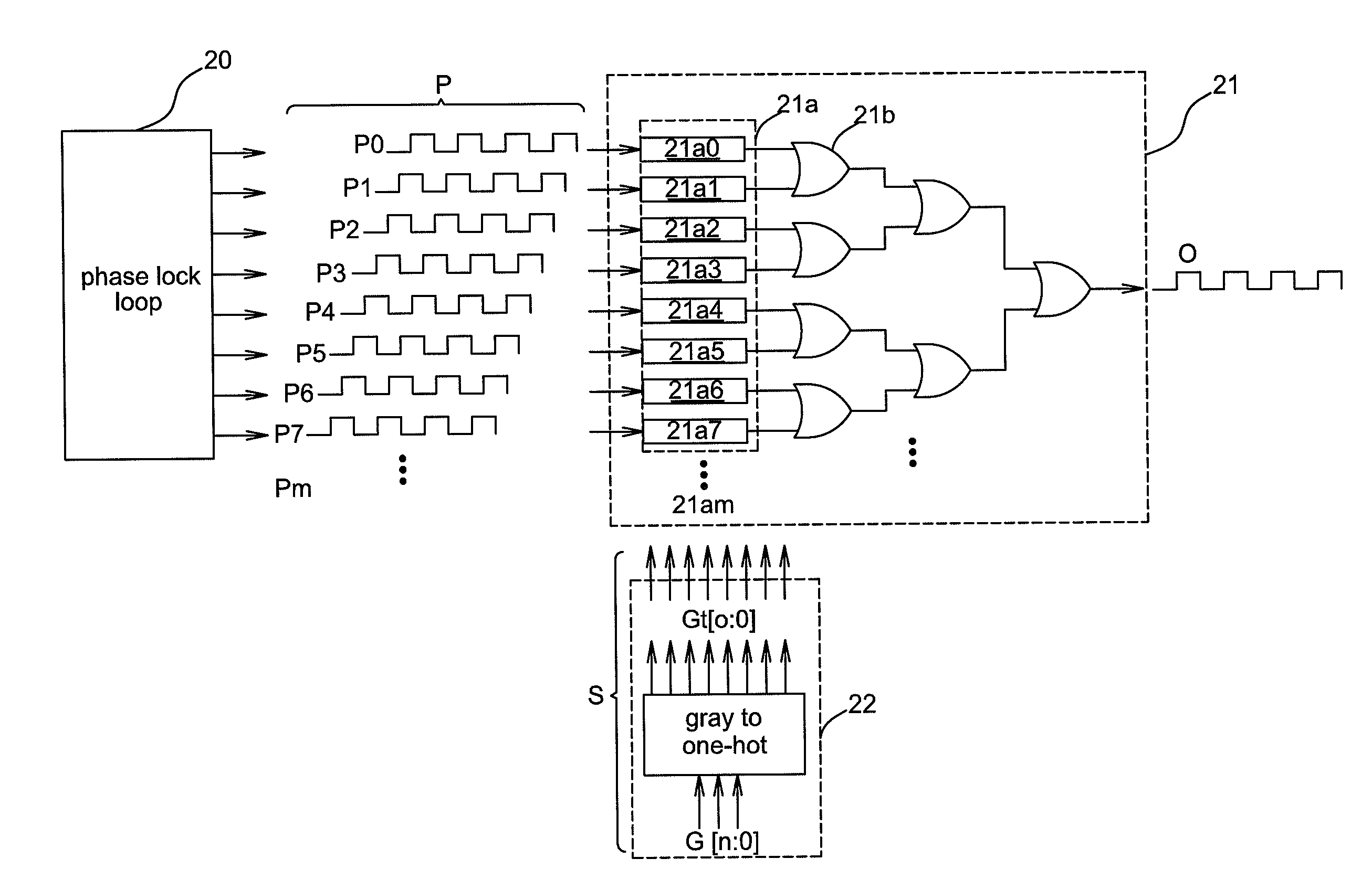
[0037]FIG. 2A shows a schematic diagram illustrating an embodiment of a multi-phase clock switching device 21 and peripheral devices thereof. In the figure, a phase lock loop 20, a multi-phase clock switching device 21, and a signal generator 22 are shown. The multi-phase clock switching device 21 receives a plurality of phase clock signals P (P0˜Pm where m is a positive integer less than infinity) generated by the phase lock loop 20 and determines how to output the phase clock signals P to generate an output clock signal O according to a switching signal S generated by the signal generator 22.
[0038]In an embodiment, the signal generator 22 may be a code conversion unit, such as a gray to one-hot conversion unit in the figure that converts the gray code G[n:0] into a binary code Gt[o:0] to generate a switching signal S with a binary code. For example, G[2:0] may be converted into Gt[7:0]. In the above, “n” and “o” are integers less than infinity and then =o=nm−1, where m is an integ...
PUM
 Abstract
Description
Claims
Application Information