Compressor with a bypass port

a compressor and bypass port technology, applied in the direction of positive displacement liquid engines, rotary piston liquid engines, pumps, etc., can solve the problem that the system in which the compressor is connected rarely operates at exactly the same conditions, and achieves improved energy efficiency rating (eer), better part-load performance, and reduced volume ratio

Active Publication Date: 2012-02-02
JOHNSON CONTROLS TYCO IP HLDG LLP
View PDF2 Cites 17 Cited by
  • Summary
  • Abstract
  • Description
  • Claims
  • Application Information

AI Technical Summary

Benefits of technology

[0009]One advantage of the present application is an improved energy efficiency rating (EER) over a fix...

Problems solved by technology

However, the system in which the compressor is connected rarely operates at exa...

Method used


Image

  • Compressor with a bypass port
  • Compressor with a bypass port
  • Compressor with a bypass port

Examples


Embodiment Construction

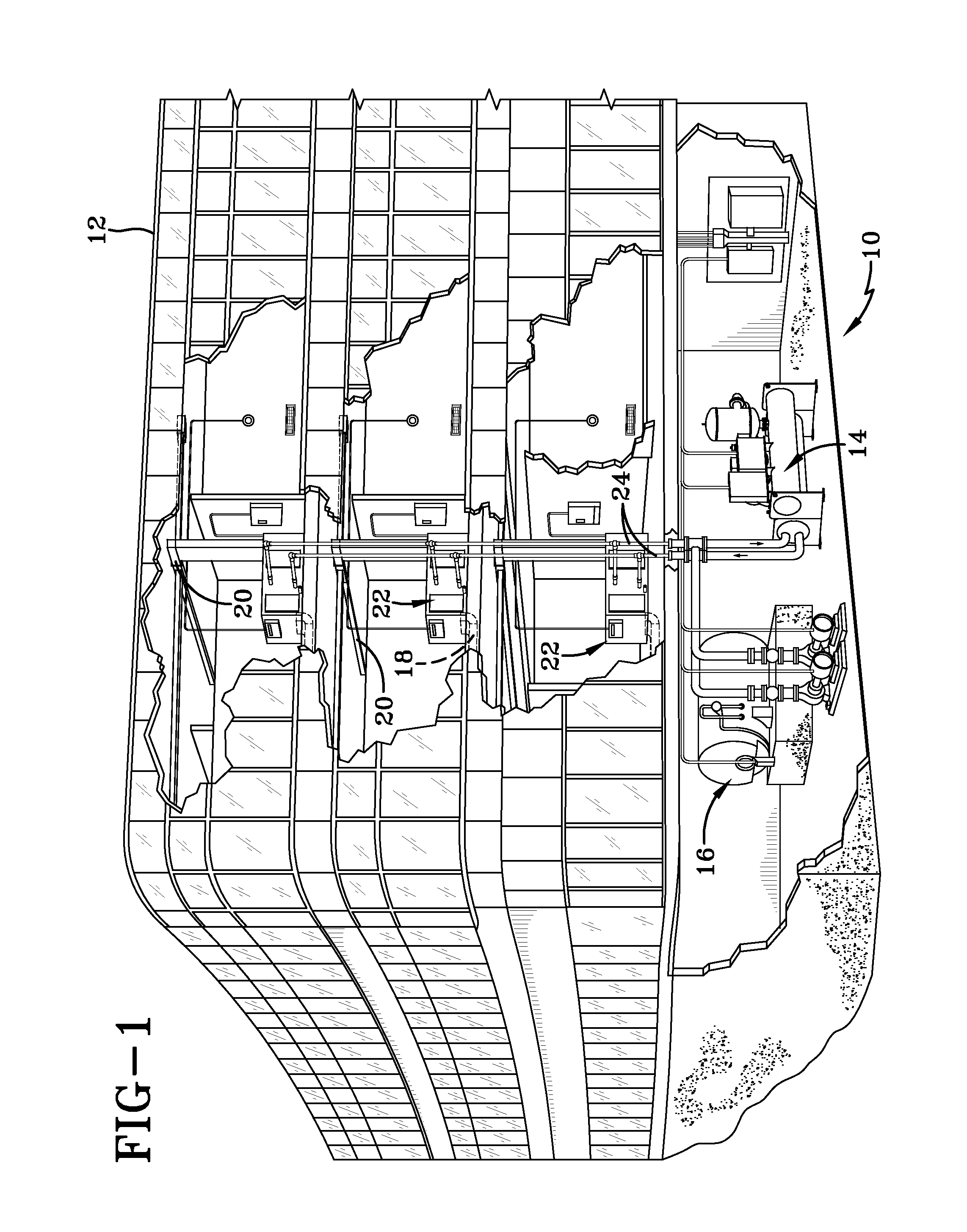
[0027]FIG. 1 shows an exemplary environment for a heating, ventilation and air conditioning (HVAC) system 10 in a building 12 for a typical commercial setting. System 10 can include a vapor compression system 14 that can supply a chilled liquid which may be used to cool building 12. System 10 can include a boiler 16 to supply heated liquid that may be used to heat building 12, and an air distribution system which circulates air through building 12. The air distribution system can also include an air return duct 18, an air supply duct 20 and an air handler 22. Air handler 22 can include a heat exchanger that is connected to boiler 16 and vapor compression system 14 by conduits 24. The heat exchanger in air handler 22 may receive either heated liquid from boiler 16 or chilled liquid from vapor compression system 14, depending on the mode of operation of system 10. System 10 is shown with a separate air handler on each floor of building 12, but it is appreciated that the components may...


PUM


Abstract

A system is provided for adjusting the volume ratio of a screw compressor. The system can use a port in a rotor cylinder to bypass vapor from the compression chamber to the discharge passage of the compressor. A valve can be used to open or close the port to obtain different volume ratios in the compressor.

Description

CROSS-REFERENCE TO RELATED APPLICATIONS[0001]This application claims priority from and the benefit of U.S. Provisional Application No. 61 / 163,647, entitled COMPRESSOR, filed Mar. 26, 2009 which is hereby incorporated by reference.BACKGROUND[0002]The application generally relates to positive-displacement compressors. The application relates more specifically to controlling the volume ratio of a screw compressor.[0003]In a rotary screw compressor, intake and compression can be accomplished by two tightly-meshing, rotating, helically lobed rotors that alternately draw gas into the threads and compress the gas to a higher pressure. The screw compressor is a positive displacement device with intake and compression cycles similar to a piston / reciprocating compressor. The rotors of the screw compressor can be housed within tightly fitting bores that have built in geometric features that define the inlet and discharge volumes of the compressor to provide for a built in volume ratio of the c...

Claims


Application Information

Patent Timeline
IPC IPC(8): F04B23/00
CPCF04C18/16F04C28/26F04C28/12F04C28/06F04C28/125F04C28/16F04C28/18
Inventor NEMIT, JR., PAULCOMSTOCK, ANGELA MARIEKOPKO, WILLIAM L.
Owner JOHNSON CONTROLS TYCO IP HLDG LLP
Why Eureka
Try Eureka