
Methods, apparatus and systems to control the tribo-electric charge of a toner material associated with a printing development system

Active Publication Date: 2012-02-02
XEROX CORP
View PDF2 Cites 1 Cited by
  • Summary
  • Abstract
  • Description
  • Claims
  • Application Information

AI Technical Summary

Benefits of technology

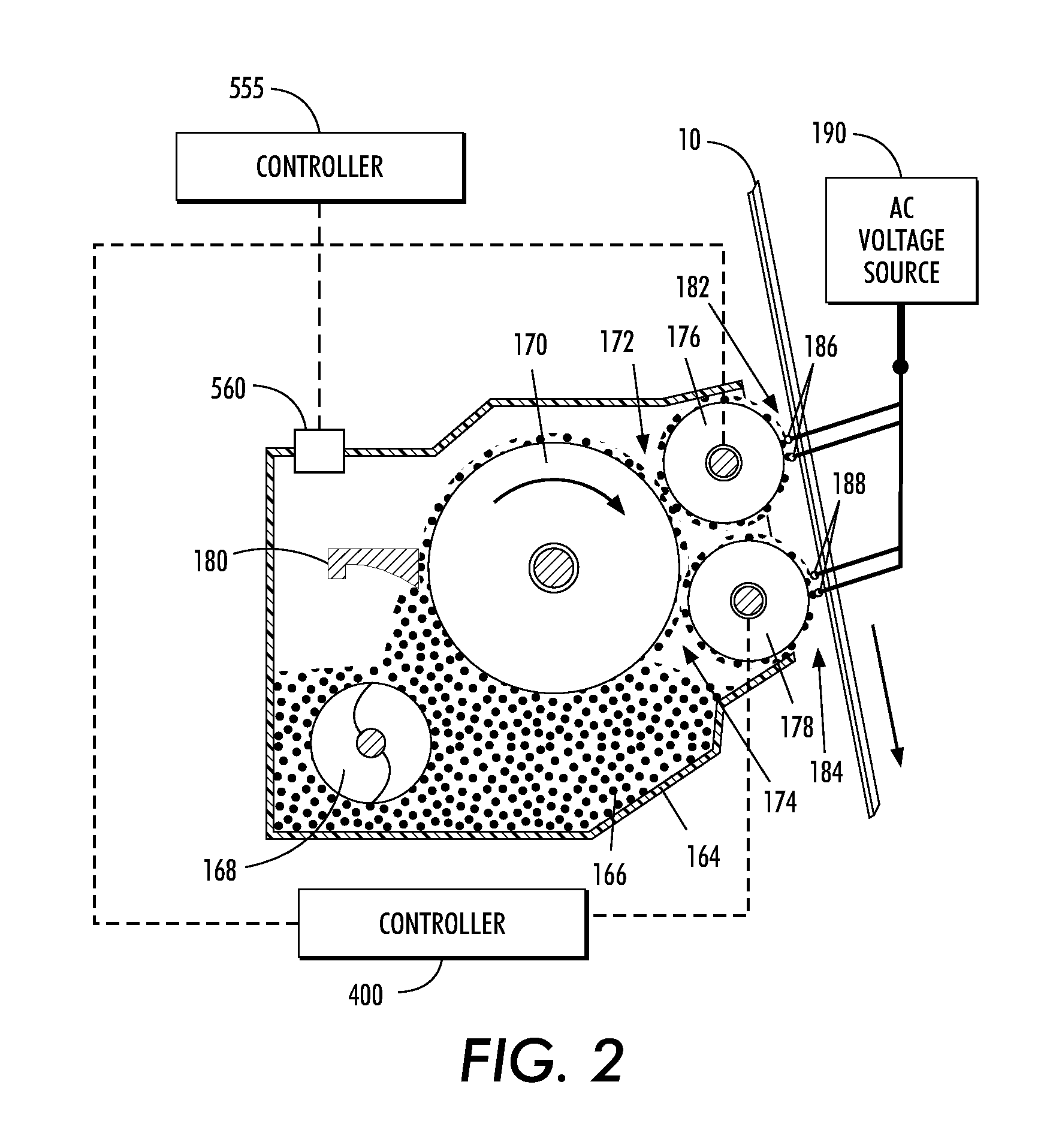
[0020]In one embodiment of this disclosure, described is a method of developing a latent image recorded on a surface using a development system, the development system including a chamber storing a supply of developer material therein, a transport member, a donor member, an electrode wire, a temperature control system configured to control a temperature associated with the developer material to a target temperature and a humidity sensor configured to measure the humidity associated with the developer material, wherein the transport member is configured to transport the developer material to the donor member, and the donor member and electrode wire are configured to form a cloud of developer material in a space between the electrode wire and the surface to develop the latent image on the surface, the method comprising a) measuring the humidity associated with the developer material; b) the temperature control system controlling the temperature of the developer material as a function of the measured humidity, the temperature of the developer material being increased as the measured humidity increases thereby increasing a tribo-electric charge associated with the development material within the chamber, and the temperature of the developer material being decreased as the measured humidity decreases thereby decreasing the tribo-electric charge associated with the developer material within the chamber; c) mixing the developer material with magnetic carrier granules, thereby producing a tribo-electrically charged developer material; d) magnetically transporting the developer material from the chamber to the transport roll; e) transporting the developer material from the transport roll to the donor roll by applying a development field voltage (Vdm) between the donor member and the transport member; and f) electrically biasing the electrode wire to detach the developer material from the donor roll to form the cloud of developer material in the space between the electrode wire and the surface to develop the latent image.
[0021]In another embodiment of this disclosure, described is an apparatus for developing a latent image recorded on a surface comprising a housing defining a chamber storing a supp

Problems solved by technology

While the IOI process provides certain benefits, such as a compact architecture, there are several challenges to its successful implementation.
In the past, Manufacturers have put limits on the acceptable customer temperature and RH extremes before installing machines.
However HVAC control is expensive and may not be available or viable in some customer locations.

Method used


Image

  • Methods, apparatus and systems to control the tribo-electric charge of a toner material associated with a printing development system
  • Methods, apparatus and systems to control the tribo-electric charge of a toner material associated with a printing development system
  • Methods, apparatus and systems to control the tribo-electric charge of a toner material associated with a printing development system

Examples


Embodiment Construction

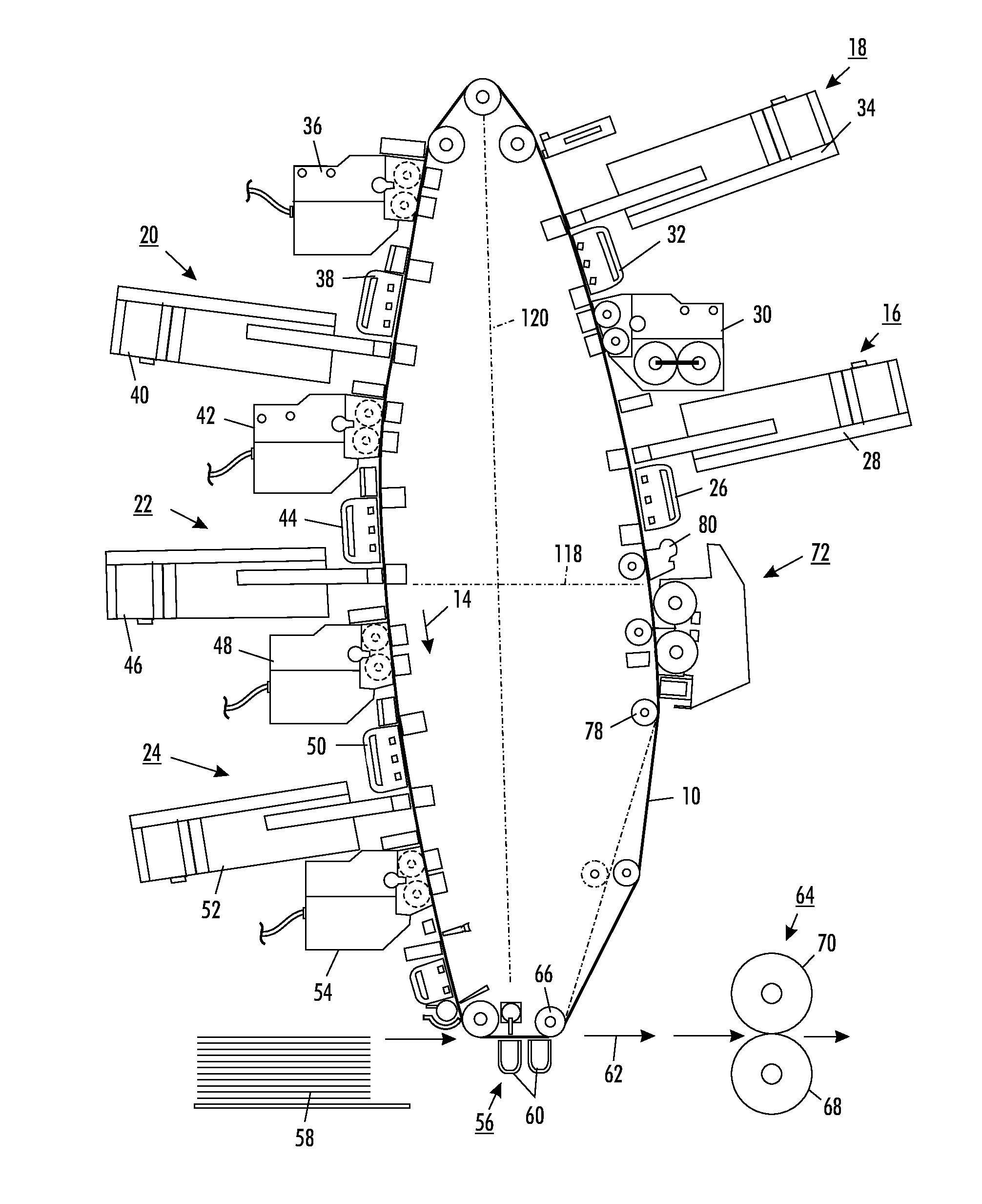
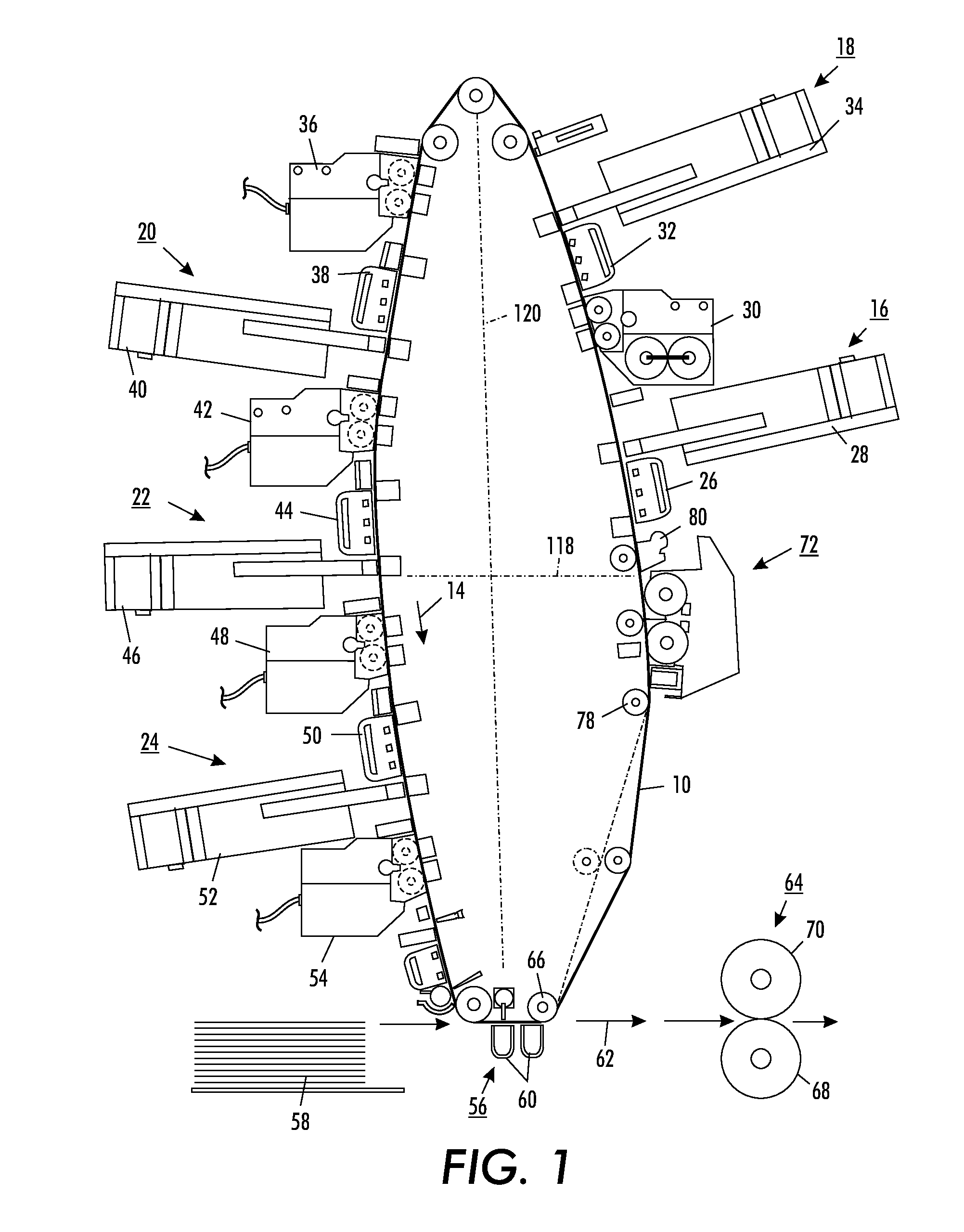
[0036]As previously stated in the background, this disclosure, and the exemplary embodiments included herein, provide printing methods, apparatus and systems to control the donor roll to mag roll development field (Vdm) as a function of the environment associated with a toner material utilized to develop a latent image recorded on a photoreceptor surface. The developed image is subsequently transferred to another substrate which may be, but not limited to, a paper sheet.

[0037]According to one aspect of this disclosure, provided is a method to update the Vdm based on a change in absolute humidity or grains of water (GOW). The change in Vdm is a function of the relationship between GOW and toner tribo-tribo goes down as GOW goes up. By adjusting the donor roll to mag roll development field (Vdm) as a function of GOW, the toner mass developed to the donor roll can be kept more constant, thereby resulting in a more consistent bed of toner entering a hybrid scavengeless development (HSD)...


PUM


Abstract

Disclosed are printing methods, apparatus and systems for developing a latent image recorded on a surface, for example, a photoreceptor with developer material. According to an exemplary embodiment, the development method applies a development field voltage between a development station donor member and a development station transport member as a function of a humidity measurement associated with the developer material, the humidity measurement providing a surrogate tribo measurement of the developer material.

Description

CROSS REFERENCE TO RELATED PATENTS AND APPLICATIONS[0001]U.S. patent application Ser. No. 12 / 821,513, filed Jun. 23, 2010, by W. Bradford Willard et al., entitled “METHODS, APPARATUS AND SYSTEMS TO CONTROL THE DONOR ROLL TO MAG ROLL DEVELOPMENT FIELD (VDM) ASSOCIATED WITH A PRINTING DEVELOPMENT SYSTEM” is totally incorporated herein by reference in its entirety.BACKGROUND[0002]Generally, the process of electrophotographic printing includes charging a photoconductive member to a substantially uniform potential to sensitize the surface thereof. The charged portion of the photoconductive surface is exposed to a light image from either a scanning laser beam, an LED source, or an original document being reproduced. This records an electrostatic latent image on the photoconductive surface. After the electrostatic latent image is recorded on the photoconductive surface, the latent image is developed. Two-component and single-component developer materials are commonly used for development. ...

Claims


Application Information

Patent Timeline
IPC IPC(8): G03G13/06G03G21/20
CPCG03G15/0803G03G2215/0643G03G2215/00776G03G2215/00772
Inventor WILLARD, W. BRADFORDSTOLL, KIMBERLY ANNESTOOKEY, DAVID R.JACOBS, PAUL L.PHELPS, ROBERT W.RAM, JYOTHSNA
Owner XEROX CORP
Learn More