
Image sensor with a gated storage node linked to transfer gate

Active Publication Date: 2020-04-16
SAMSUNG ELECTRONICS CO LTD
View PDF0 Cites 2 Cited by
  • Summary
  • Abstract
  • Description
  • Claims
  • Application Information

AI Technical Summary

Benefits of technology

This patent provides a way to increase the storage capacity of each pixel in an image sensor. It introduces a global electronic shutter that allows for double sampling and a reduction of kTC noise. Additionally, the patent proposes a procedure of operating the CMOS pixel with the shutter gate open during a charge integration period, which results in a larger charge storage for the pixel.

Problems solved by technology

Imager pixels, including CMOS imager pixels typically have low signal to noise ratios and narrow dynamic range because of their inability to fully collect, transfer and store the electric charge collected by the photosensitive area of the photosensor.
In addition, the pixels are subject to kTC noise, which is a thermal dependent noise generated during the reset of the pixel.
In addition, the use of additional gates to increase the functional operations of the pixel (i.e., electronic shuttering) increases the size of the pixel or reduces the fill factor of the pixel.

Method used


Image

  • Image sensor with a gated storage node linked to transfer gate
  • Image sensor with a gated storage node linked to transfer gate
  • Image sensor with a gated storage node linked to transfer gate

Examples


Embodiment Construction

[0025]In the following detailed description, reference is made to the accompanying drawings, which are a part of the specification, and in which is shown by way of illustration various embodiments whereby the invention may be practiced. These embodiments are described in sufficient detail to enable those skilled in the art to make and use the invention. It is to be understood that other embodiments may be utilized, and that structural, logical, and electrical changes, as well as changes in the materials used, may be made without departing from the spirit and scope of the present invention. Additionally, certain processing steps are described and a particular order of processing steps is disclosed; however, the sequence of steps is not limited to that set forth herein and may be changed as is known in the art, with the exception of steps or acts necessarily occurring in a certain order.

[0026]The terms “wafer” and “substrate” are to be understood as interchangeable and as including si...


PUM


Abstract

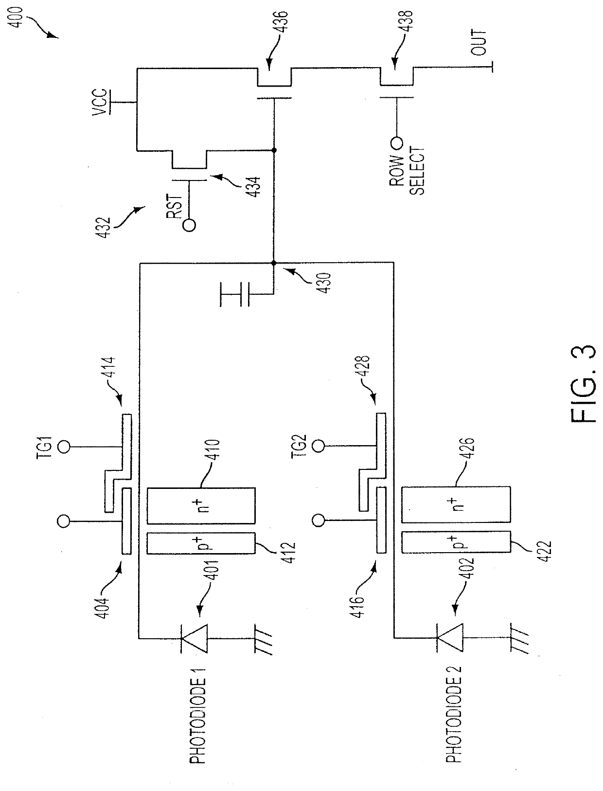
A CMOS imaging system with increased charge storage of pixels yet decreased physical size, kTC noise and active area. A storage node is connected to the transfer gate and provides a storage node for a pixel, allowing for kTC noise reduction prior to readout. The pixel may be operated with the shutter gate on during the integration period to increase the amount of time for charge storage by a pixel.

Description

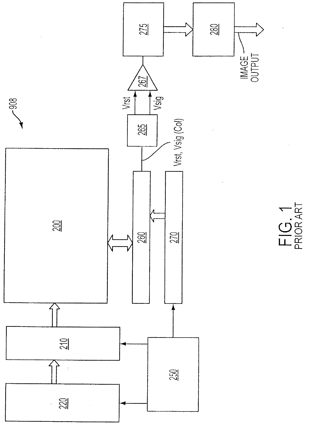
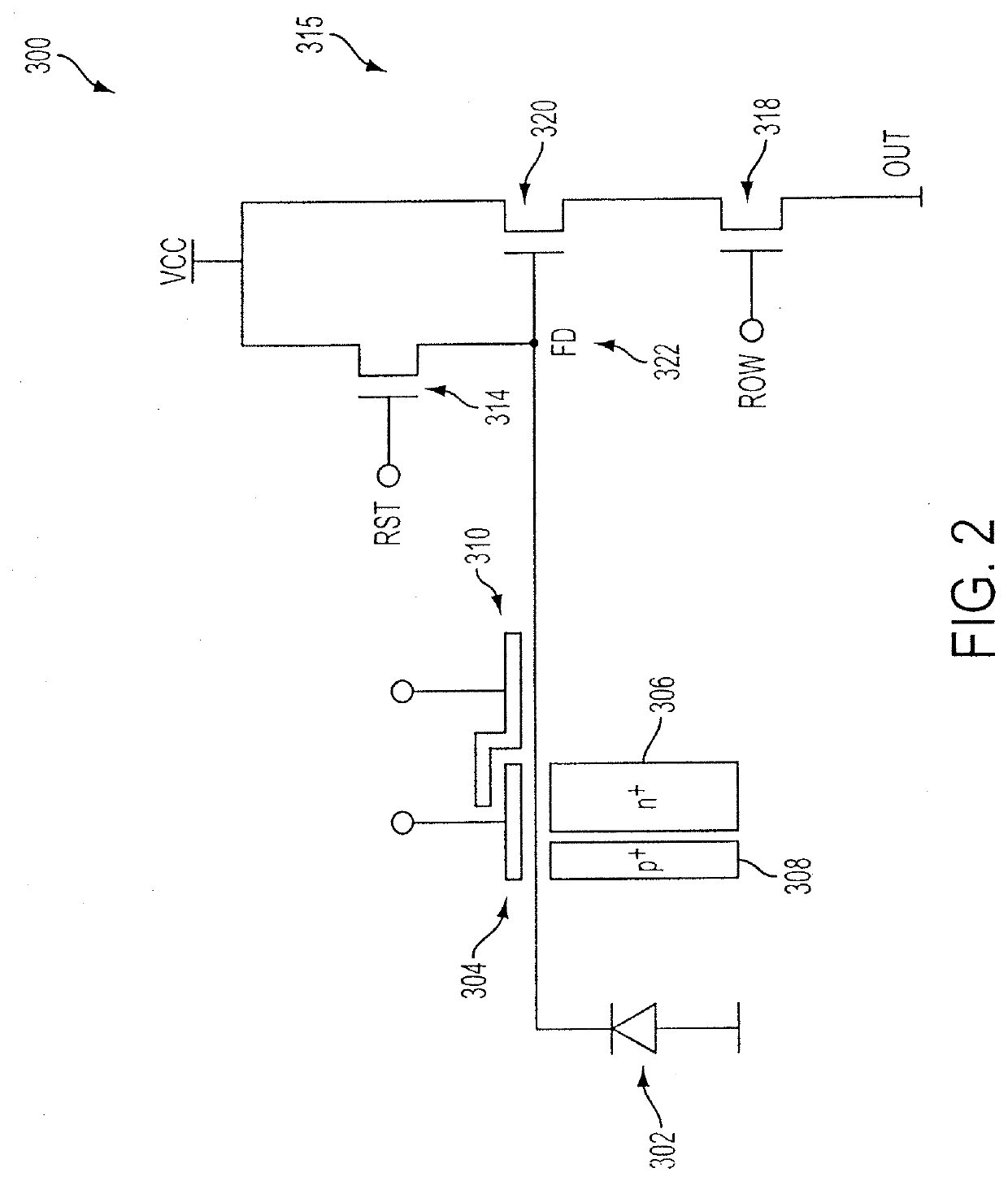
CROSS-REFERENCE TO RELATED APPLICATIONS[0001]This application is a continuation of U.S. patent application Ser. No. 13 / 309,199, filed on Dec. 1, 2011, now U.S. Pat. No. 8,471,938, granted Jun. 25, 2013, which is a continuation of U.S. patent application Ser. No. 12 / 232,994, filed on Sep. 26, 2008, now U.S. Pat. No. 8,081,249, granted Dec. 20, 2011, which is a divisional of U.S. patent application Ser. No. 10 / 721,191, filed on Nov. 26, 2003, now U.S. Pat. No. 7,443,437, granted Oct. 28, 2008, the subject matter of each of which is incorporated in its entirety by reference herein.FIELD OF THE INVENTION[0002]The invention relates generally to improving the charge storage capacity of an imager pixel.BACKGROUND OF THE INVENTION[0003]An imager, for example, a CMOS imager includes a focal plane array of pixel cells; each cell includes a photosensor, for example, a photogate, photoconductor or a photodiode overlying a substrate for producing a photo-generated charge in a doped region of the...

Claims


Application Information

Patent Timeline
IPC IPC(8): H01L27/148H04N5/3745H04N5/363H04N3/14H04N3/15
CPCH01L27/148H04N5/37457H04N5/363H04N25/65H04N25/778
Inventor ALTICE JR., PETER P.MCKEE, JEFFERY A.
Owner SAMSUNG ELECTRONICS CO LTD
Learn More