Electrode attachment state determination system, electrode attachment state determination method, and program thereof

a technology of electrode attachment and state determination, applied in the field of electroencephalogram measurement, can solve the problems of user burden, wear stability, and the act of applying paste on the electrode also presents a burden on the user, and achieve the effect of stable electroencephalogram measuremen

Inactive Publication Date: 2012-02-02
PANASONIC INTELLECTUAL PROPERTY MANAGEMENT CO LTD
View PDF9 Cites 17 Cited by
  • Summary
  • Abstract
  • Description
  • Claims
  • Application Information

AI Technical Summary

Benefits of technology

[0041]According to the present invention, in an electrode attachment state determination system in which electrodes are used, it is possible to detect insufficiencies in electrode attachment and identify which one of a plurality of electrodes has become insufficient, thus enabling stable electroencephalogram measurements.

Problems solved by technology

Such manners of use, which require use of paste or help of someone else for wearing ease, will present burdens to the user an electroencephalogram interface is to be used in a daily-life environment.
Moreover, the act of applying paste onto the electrodes also presents a burden on the user.
Furthermore, after the device is detached, the paste will remain where the electrodes have been placed, and thus needs to be wiped off by the user himself or herself.
However, use of dry electrodes presents a problem in wearing stability.
As a result, problems may occur, such as the electrode position changing even though contact with the skin may be maintained (“electrode shifting”), or a space being created between the skin and the electrode to disable electroencephalogram measurement (“lifting”, “disengagement”).
When electrode shifting occurs, the skin will be rubbing against the electrode surface, so that noises may likely be mixed.
If an electrode disengagement occurs, electroencephalogram measurement will be so affected that it may not be continued.
Since the user will not always be in a resting state but will undergo various motions in a daily-life environment, insufficiencies concerning electrode contact, such as electrode shifting and electrode disengagement, are probably likely to occur.
However, any of the techniques of the aforementioned conventional approaches has a problem of being unable to identify which electrode is suffering from an insufficiency in the electroencephalogram measurements in a daily-life environment.
However, the state of electrode attachment will change over time in a daily-life environment, and thus the frequency with which to confirm the state of attachment should increase, but stopping the electroencephalogram measurement each time before a contact resistance measurement will be considerably inconvenient.
Thus, in Japanese Examined Utility Model Publication No. 7-3347, and Japanese Laid-Open Patent Publication No. 2006-212348, no consideration is given to the detection of insufficient electrodes in an environment where the state of electrode attachment may change, making it difficult to identify which electrode has become insufficient.
However, it is still impossible to identify which electrode is suffering from insufficient wearing.
Note that, even by using paste, electrode shifting and electrode disengagement cannot be completely eliminated.
Therefore, the above-described problems of the conventional techniques are not confined to dry electrodes alone.
Also in the case where electrode shifting or electrode disengagement occurs in an electrode where paste is applied, it is still necessary to identify which electrode has become insufficient.

Method used


Image

  • Electrode attachment state determination system, electrode attachment state determination method, and program thereof
  • Electrode attachment state determination system, electrode attachment state determination method, and program thereof
  • Electrode attachment state determination system, electrode attachment state determination method, and program thereof

Examples


embodiment 1

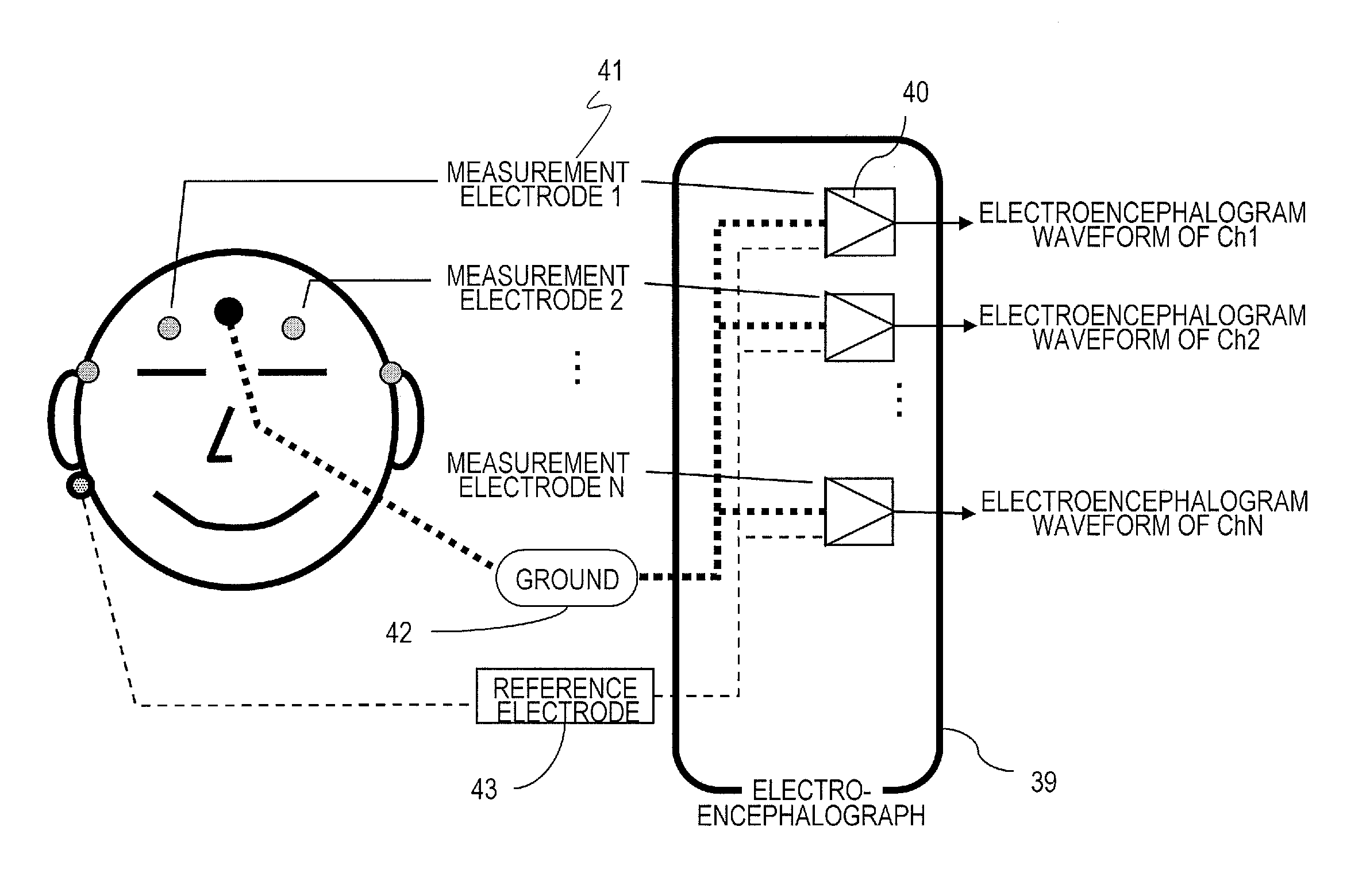
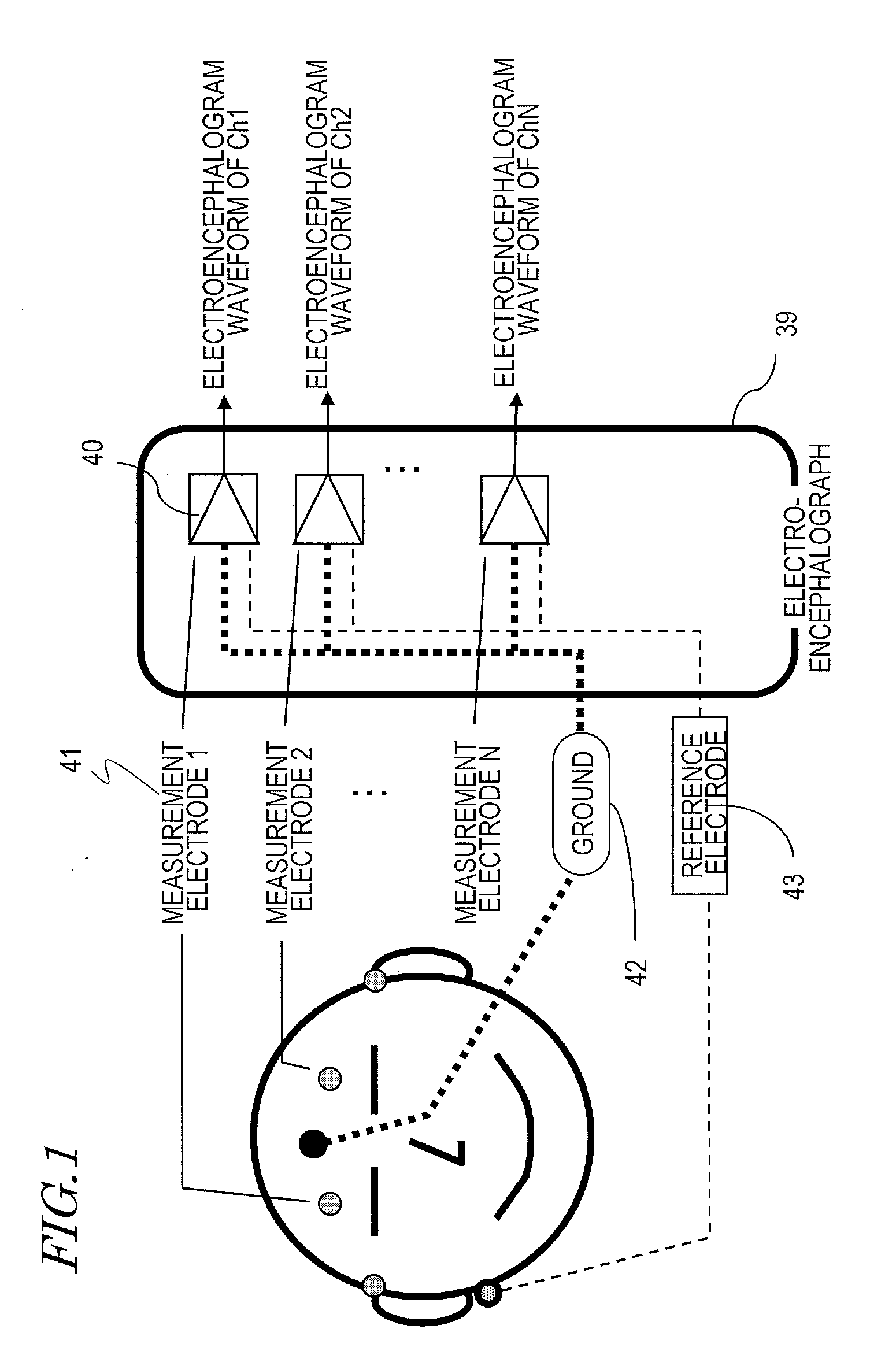
[0107]FIG. 7 shows the functional block construction of an electrode attachment state determination system 20 according to the present embodiment. FIG. 8 shows an exemplary shape of a device which embodies the electrode attachment state determination system 20 in the form of an HMD. FIG. 9 shows an exemplary hardware construction of the electrode attachment state determination system 20. Among the constituent elements shown in each figure, like constituent elements are denoted by like reference numerals.

[0108]In the present specification, the electrode attachment state determination system 20 will be described on the basis of an HMD shape shown in FIG. 8. The respective portions of the HMD are expressed by using terms that indicate eyeglass portions. FIG. 10 shows the names of respective portions of eyeglasses. Portions which hang on the ears of a user 10 to fix the HMD main body will be referred to as “endpiece portions”. Portions which come in contact with the nose of the user 10 ...

embodiment 2

[0206]With the construction of Embodiment 1, when the state of attachment of an electrode becomes insufficient, the user 10 is able to know the type of electrode which is insufficiently worn, thus realizing a determination of the state of electrode attachment.

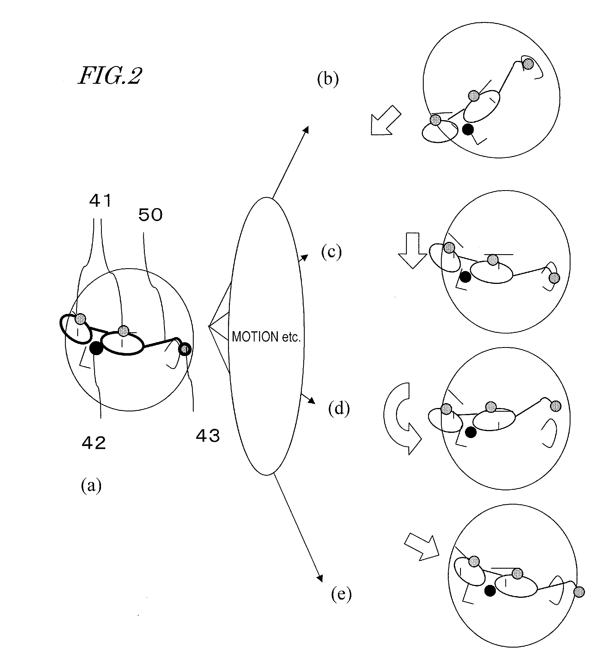
[0207]However, in a daily-life environment, it is expected that there are frequent chances for electrodes to become insufficient under the influence of the motions of the user 10, etc. Therefore, every time the user 10 undergoes a motion, a notice of an insufficient electrode is given by the construction of Embodiment 1, thus making it necessary for the user 10 to correct the electrode state.

[0208]Thus, what is needed is a function of, after detecting an insufficient wearing of an electrode, automatically restoring from the electrode insufficiency state to enable continued electroencephalogram measurement. The automatic restoration from an electrode insufficiency state is made by replacing an electrode which has become insuffic...


PUM


Abstract

An electrode attachment state determination system includes: an electroencephalogram measurement section for measuring an electroencephalogram signal of a user by using at least one set of electrodes including a ground electrode, a reference electrode, and a measurement electrode; a frequency analysis section for performing a frequency analysis of the electroencephalogram signal; an insufficient electrode determination section for extracting at least one parameter of a total frequency power and a noise amount from a result of the frequency analysis, and through a comparison of a value of the parameter against a predetermined threshold value, determining whether the ground electrode, the reference electrode, or the measurement electrode has an insufficient state of attachment; and an output section for, when an insufficient state of attachment is determined, presenting information indicating the insufficient state of electrode attachment to the user.

Description

[0001]This is a continuation of International Application No. PCT / JP2010 / 006828, with an international filing date of Nov. 22, 2010, which claims priority of Japanese Patent Application No. 2009-283678, filed on Dec. 15, 2009, the contents of which are hereby incorporated by reference.BACKGROUND OF THE INVENTION[0002]1. Field of the Invention[0003]The present invention relates to a technique of, in an electroencephalogram measurement system which determines a state or intent of a user from a characteristic signal of the electroencephalogram of the user and feeds back the result of determination, determining a state of attachment of the electrodes which are utilized for electroencephalogram measurement.[0004]2. Description of the Related Art[0005]Conventionally, medical institutions have utilized electroencephalograms for diagnosis of epilepsy, Alzheimer's disease, and the like. On the other hand, there have been attempts at developing an electroencephalogram interface for inferring ...

Claims


Application Information

Patent Timeline
Patent Type & Authority Applications(United States)
IPC IPC(8): A61B5/0478A61B5/374
CPCA61B5/04004A61B5/0478A61B5/6803A61B5/6843A61B2560/0276A61B5/048A61B2562/0215A61B5/30A61B5/374A61B5/291
Inventor TERADA, YOSHIHISAMORIKAWA, KOJI
Owner PANASONIC INTELLECTUAL PROPERTY MANAGEMENT CO LTD
Why Eureka
Try Eureka