Devices and methods for non-invasive capacitive electrical stimulation and their use for vagus nerve stimulation on the neck of a patient

a capacitive electrical stimulation and patient technology, applied in the field of energy impulse delivery, can solve the problems of inability to fully realize the function of other tissues, and inability to fully realize the function of the other tissue,

Active Publication Date: 2012-02-02
ELECTROCORE
View PDF6 Cites 124 Cited by
  • Summary
  • Abstract
  • Description
  • Claims
  • Application Information

AI Technical Summary

Benefits of technology

[0024]The source of power supplies a pulse of electric charge to the electrodes, such that the electrodes produce an electric current and / or an electric field within the patient. The stimulator is configured to induce a peak pulse voltage sufficient to produce an electric field in the vicinity of a nerve such as a vagus nerve, to cause the nerve to depolarize and reach a threshold for action potential propagation. By way of example, the threshold electric field for stimulation of the nerve may be about 8 V / m at 1000 Hz. For example, the device may produce an electric field within the patient of about 10 to 600 V / m and an electrical field gradient of greater than 2 V / m / mm. Current passing through an electrode may be about 0 to 40 mA, with voltage across the electrodes of 0 to 30 volts. The current is passed through the electrodes in bursts of pulses. There may be 0 to 30 pulses per burst, preferably about 4 to 10 pulses and more preferably five pulses. Each pulse within a burst has a duration of 20 to 1000 microseconds, preferably 100-400 microseconds and more preferably about 200 microseconds. A burst followed by a silent inter-burst interval repeats at 1 to 5000 bursts per second (bps), preferably at 15-50 bps. The preferred shape of each pulse is a full sinusoidal wave. The preferred stimulator shapes an elongated electric field of effect that can be oriented parallel to a long nerve, such as a vagus nerve in the patient's neck. By selecting a suitable waveform to stimulate the nerve, along with suitable parameters such as current, voltage, pulse width, pulses per burst, inter-burst interval, etc., the stimulator produces a correspondingly selective physiological response in an individual patient. Such a suitable waveform and parameters are simultaneously selected to avoid substantially stimulating nerves and tissue other than the target nerve, particularly avoiding the stimulation of nerves that produce pain.

Problems solved by technology

A variety of techniques and mechanisms have been designed to produce focused lesions directly in target nerve tissue, but collateral damage is inevitable.
In many cases, these medicinal approaches have side effects that are either unknown or quite significant.
Unfortunately, the beneficial outcomes of surgery and medicines are often realized at the cost of function of other tissues, or risks of side effects.
While the therapeutic results of deep brain stimulation are promising, significant complications may arise from the implantation procedure, including stroke induced by damage to surrounding tissues and the neuro-vasculature.
Despite its attractiveness, non-invasive electrical stimulation of a nerve is not always possible or practical.
This is primarily because the current state of the art may not be able to stimulate a deep nerve selectively or without producing excessive pain, since the stimulation may unintentionally stimulate nerves other than the nerve of interest, including nerves that cause pain.
For some other electrotherapeutic applications, it has also been difficult to perform non-invasive stimulation of a nerve, in lieu of stimulating that nerve invasively.
Despite their advantage as being non-surgical, such methods nevertheless exhibit other disadvantages associated with invasive procedures.
However, because such non-invasive VNS occurs at a location other than the neck, it is not directly comparable to invasive VNS in the neck, for which therapeutic results are well-documented.

Method used


Image

  • Devices and methods for non-invasive capacitive electrical stimulation and their use for vagus nerve stimulation on the neck of a patient
  • Devices and methods for non-invasive capacitive electrical stimulation and their use for vagus nerve stimulation on the neck of a patient
  • Devices and methods for non-invasive capacitive electrical stimulation and their use for vagus nerve stimulation on the neck of a patient

Examples


Embodiment Construction

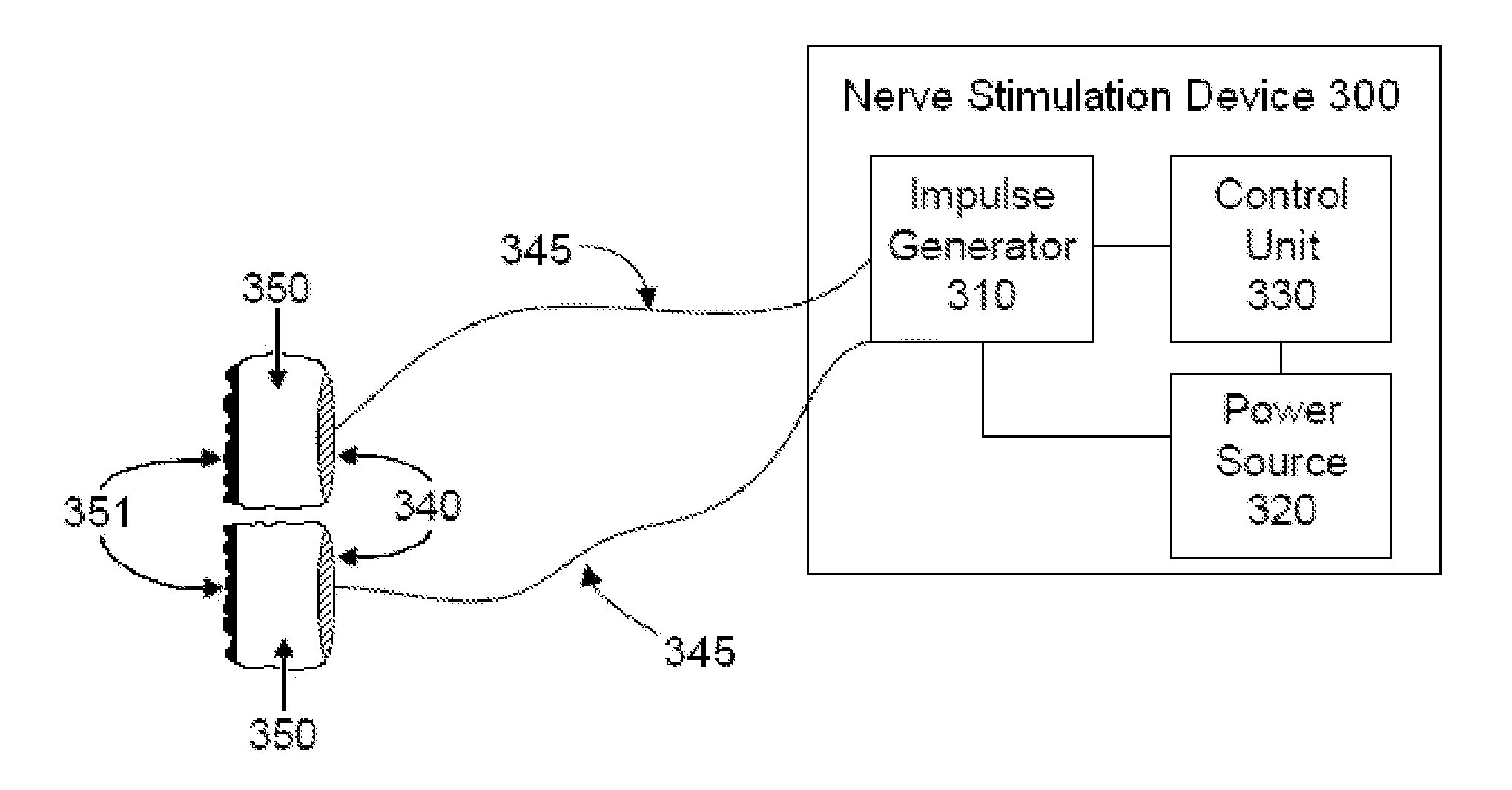
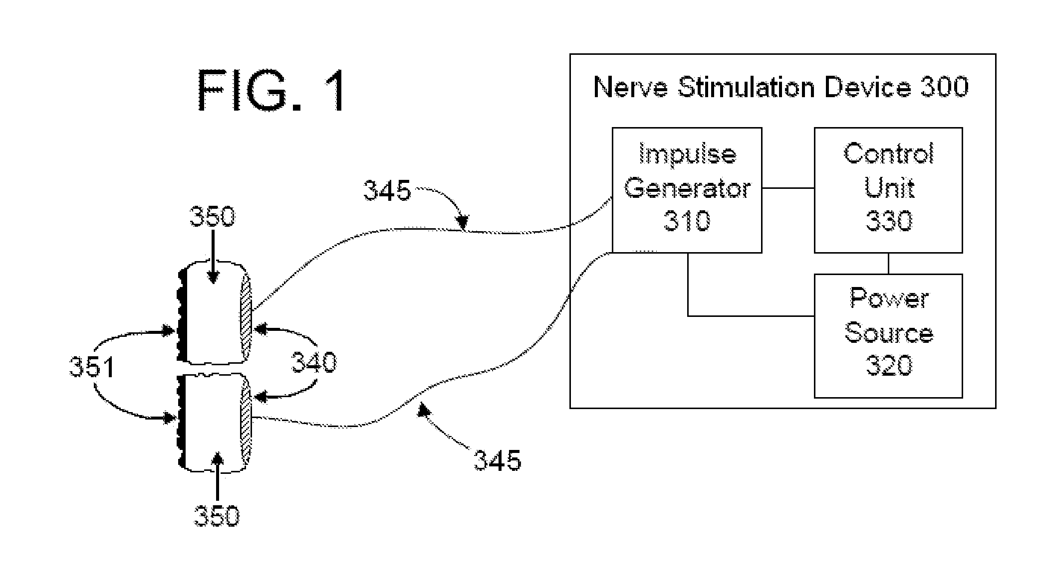
[0036]In the present invention, energy is transmitted non-invasively to a patient. The invention is particularly useful for producing applied electrical impulses that interact with the signals of one or more nerves to achieve a therapeutic result. In particular, the present disclosure describes devices and methods to stimulate a vagus nerve non-invasively at a location on the patient's neck.

[0037]There is a long-felt but unsolved need to stimulate the vagus nerve electrically in the neck, totally non-invasively, selectively, and essentially without producing pain. As described below, this is evidenced by the failure of others to solve the problem that is solved by the present invention, such that investigators abandoned the attempt to non-invasively stimulate electrically in the neck, in favor of stimulating the vagus nerve at other anatomical locations, or in favor of stimulating the vagus nerve non-electrically. Japanese patent application JP2009233024A with a filing date of Mar. ...


PUM


Abstract

A non-invasive electrical stimulation device shapes an elongated electric field of effect that can be oriented parallel to a long nerve, such as a vagus nerve in a patient's neck, producing a desired physiological response in the patient. The stimulator comprises a source of electrical power, at least one electrode and a continuous electrically conducting medium in which the electrode(s) are in contact. The stimulation device is configured to produce a peak pulse voltage that is sufficient to produce a physiologically effective electric field in the vicinity of a target nerve, but not to substantially stimulate other nerves and muscles that lie between the vicinity of the target nerve and patient's skin. Current is passed through the electrodes in bursts of preferably five sinusoidal pulses, wherein each pulse within a burst has a duration of preferably 200 microseconds, and bursts repeat at preferably at 15-50 bursts per second.

Description

CROSS REFERENCE TO RELATED APPLICATIONS[0001]This application is a continuation-in-part of U.S. patent application Ser. No. 13 / 183,765 filed Jul. 15, 2011 which claims the benefit of priority of U.S. Provisional Patent Application No. 61 / 488,208 filed May 20, 2011 and is a continuation-in-part to U.S. patent application Ser. No. 13 / 183,721 filed Jul. 15, 2011, which claims the benefit of priority of U.S. Provisional Patent Application No. 61 / 487,439 filed May 18, 2011 and is a continuation-in-part of U.S. patent application Ser. No. 13 / 109,250 filed May 17, 2011, which claims the benefit of priority of U.S. Provisional Patent Application No. 61 / 471,405 filed Apr. 4, 2011 and is a continuation-in-part of U.S. patent application Ser. No. 13 / 075,746 filed Mar. 30, 2011, which claims the benefit of priority of U.S. provisional patent application 61 / 451,259 filed Mar. 10, 2011 and is a continuation-in-part of U.S. patent application Ser. No. 13 / 005,005 filed Jan. 12, 2011, which is a con...

Claims


Application Information

Patent Timeline
Patent Type & Authority Applications(United States)
IPC IPC(8): A61N1/36
CPCA61N1/40A61N2/02A61N2/008A61N2/006A61N1/36034A61N1/0456
Inventor SIMON, BRUCEERRICO, JOSEPHRAFFLE, JOHN T.
Owner ELECTROCORE
Why Eureka
Try Eureka