Systems and methods for generating and utilizing electrical signatures for electrical and electronic equipment

a technology of electrical signatures and electrical equipment, applied in the direction of computer control, process and machine control, instruments, etc., can solve the problems of insufficient integration of known energy management and control systems into the fabric of control panels and wiring, inability to provide a monitoring device with a mechanism, and inability to integrate energy management and control systems in sufficient depth inside electrical panels

Inactive Publication Date: 2012-02-02
ENSITE POWER INC
View PDF6 Cites 171 Cited by
  • Summary
  • Abstract
  • Description
  • Claims
  • Application Information

AI Technical Summary

Benefits of technology

[0009]A PeakPower Commander System provides local or remote monitoring and / or control of power and other utilities and devices, including security, for commercial, industrial or residential applications. Energy Sensors may plug into a circuit breaker panel with existing Breakers, or snap onto the wiring near a piece of equipment in accordance with various disclosed embodiments set forth below.

Problems solved by technology

Previously known energy management and control systems are not sufficiently integrated into the fabric of the control panels and wiring at a circuit level.
Previously known energy management and control systems are incapable of sufficient integration inside electrical panels.
For example, such systems provide no mechanism by which a monitoring device may clamp on to a wire innocuously with no wires hanging out in order to meet common Fire Marshal requirements for safety.
Previously known clamp-on CTs (Current Transformers) installed into a facility and its circuits to characterize energy usage must be removed before the Fire Marshal arrives because such previously known clamp-on CTs result in a “rats nest” of wiring and instrumentation hanging out of the panels or off the wiring which cannot pass a Fire Marshal inspection, and thus, does not permit permanent on-going usage and installation.
Previously known energy management and control systems lack energy monitoring current transformer based units with algorithms to perform statistical analysis.

Method used


Image

  • Systems and methods for generating and utilizing electrical signatures for electrical and electronic equipment
  • Systems and methods for generating and utilizing electrical signatures for electrical and electronic equipment
  • Systems and methods for generating and utilizing electrical signatures for electrical and electronic equipment

Examples


Embodiment Construction

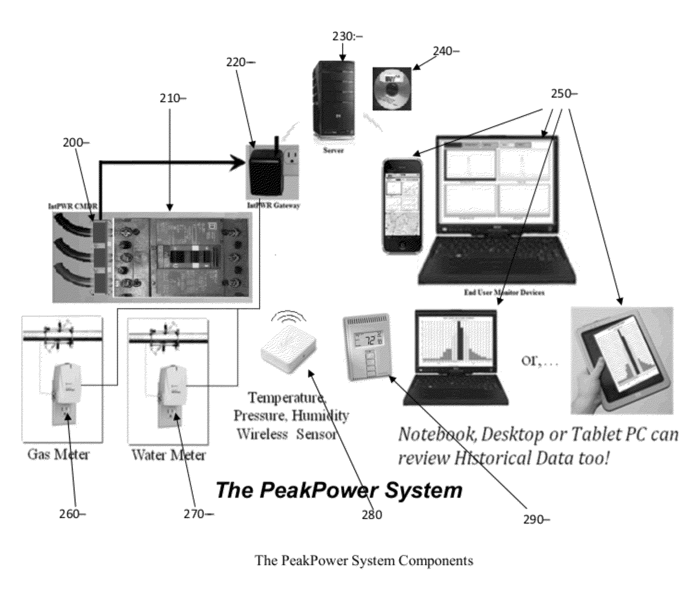
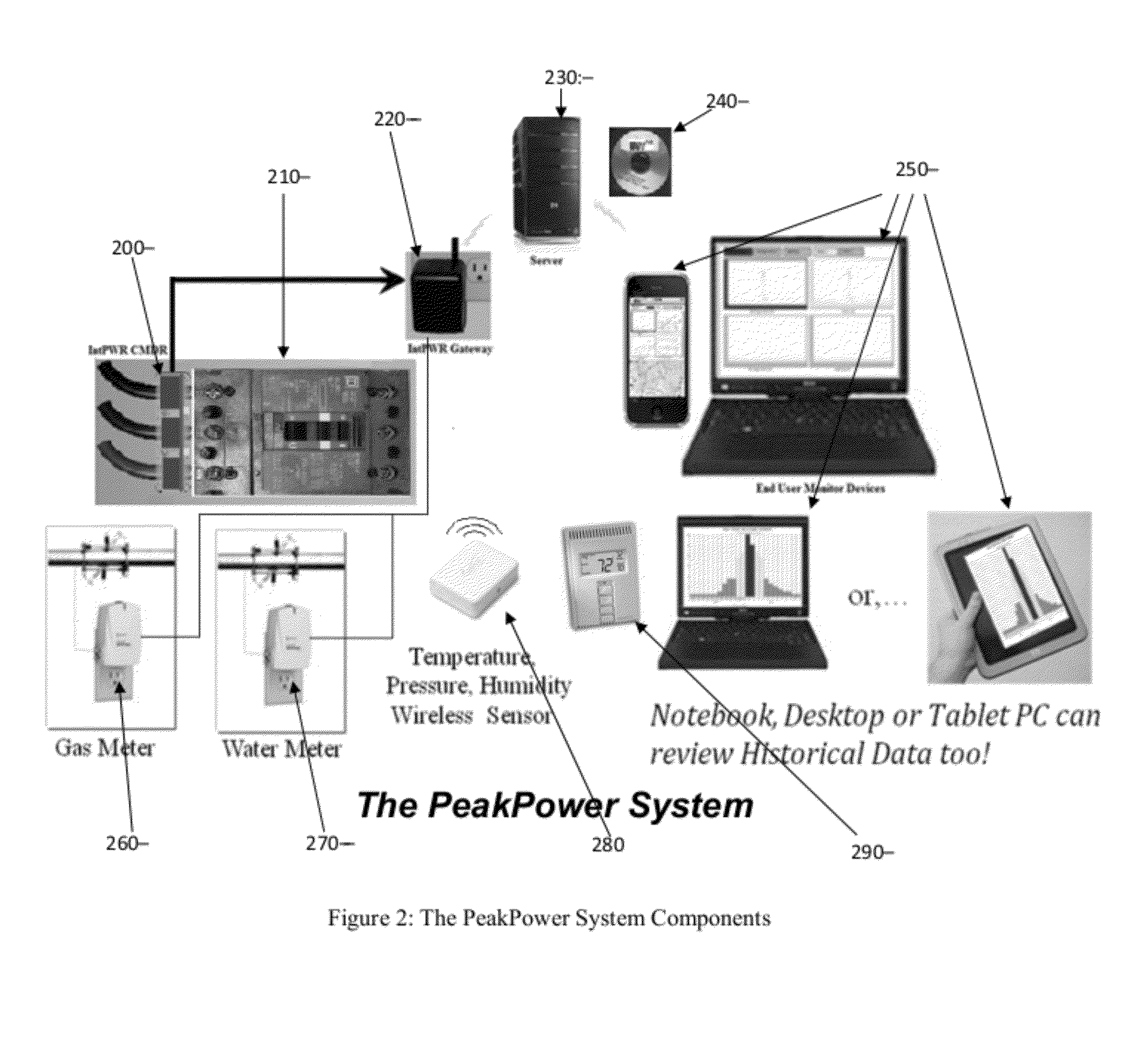
[0041]Described herein are systems, devices, methods, and apparatuses for implementing a roll-lock snap-on current transformer and associated and complementary PeakPower Energy Management and Control Systems.

[0042]In a particular embodiment, a PeakPower Energy Management and Control System has one or more roll-lock snap-on current transformer power monitoring devices, each to avoid interrupting power when installing current and / or power monitors. Each roll-lock snap-on current transformer power monitoring device may be snapped onto existing power wires inside a power panel or near equipment being monitored without disconnecting any wires or turning off power. Each roll-lock snap-on current transformer power monitoring device may be utilized in standalone mode as well as within a PeakPower Energy Management and Control System in accordance with disclosed embodiments. Each roll-lock snap-on current transformer power monitoring device may communicate via the power lines (via a Power Li...


PUM


Abstract

A PeakPower Energy Management and Control System having one or more roll-lock snap-on current transformer power monitoring devices, each to avoid interrupting power when installing current and/or power monitors. Each roll-lock snap-on current transformer power monitoring device may be snapped onto existing power wires inside a power panel or near equipment being monitored without disconnecting any wires or turning off power. Each roll-lock snap-on current transformer power monitoring device may be utilized in standalone mode as well as within a PeakPower Energy Management and Control System in accordance with disclosed embodiments. Each roll-lock snap-on current transformer power monitoring device may communicate via the power lines (Power Line Controller) or communicate via wireless using an integrated microprocessor based RF transceiver.

Description

CLAIM OF PRIORITY[0001]This continuation-in-part application is related to, and claims priority to, U.S. Patent Application Serial No. 13 / 112,388, entitled “ROLL-LOCK SNAP-ON CURRENT TRANSFORMER” filed on May 20, 2011, having Attorney Docket No. 9159P001 which is a U.S. non-provisional application that claims priority to U.S. Provisional Patent Application Ser. No. 61 / 347,184 entitled “ROLL-LOCK SNAP-ON CURRENT TRANSFORMER,” filed on May 21, 2010; each of which are hereby incorporated by reference herein as though set forth in full.COPYRIGHT NOTICE[0002]A portion of the disclosure of this patent document contains material which is subject to copyright protection. The copyright owner has no objection to the facsimile reproduction by anyone of the patent document or the patent disclosure, as it appears in the Patent and Trademark Office patent file or records, but otherwise reserves all copyright rights whatsoever.TECHNICAL FIELD[0003]Embodiments of the present invention relate genera...

Claims


Application Information

Patent Timeline
Patent Type & Authority Applications(United States)
IPC IPC(8): G06F1/32G05D23/19G06F15/18
CPCG01R1/22G01R15/183Y02E60/727Y04S10/26G05B15/02Y02E40/70Y02E60/00Y04S10/00Y04S10/22
Inventor DAVIS, EDWARD L.
Owner ENSITE POWER INC
Why Eureka
Try Eureka