

Method of Controlling Energy Buffer Drive
a technology of energy buffer drive and energy buffer drive, which is applied in the direction of machine/engine, process and machine control, instruments, etc., can solve the problems of insufficient power for driving the input shaft, the output power of the engine cannot increase rapidly, and the output power of the engine cannot be rapidly increased
- Summary
- Abstract
- Description
- Claims
- Application Information
AI Technical Summary
Benefits of technology
Problems solved by technology
Method used
Image

Examples
first embodiment
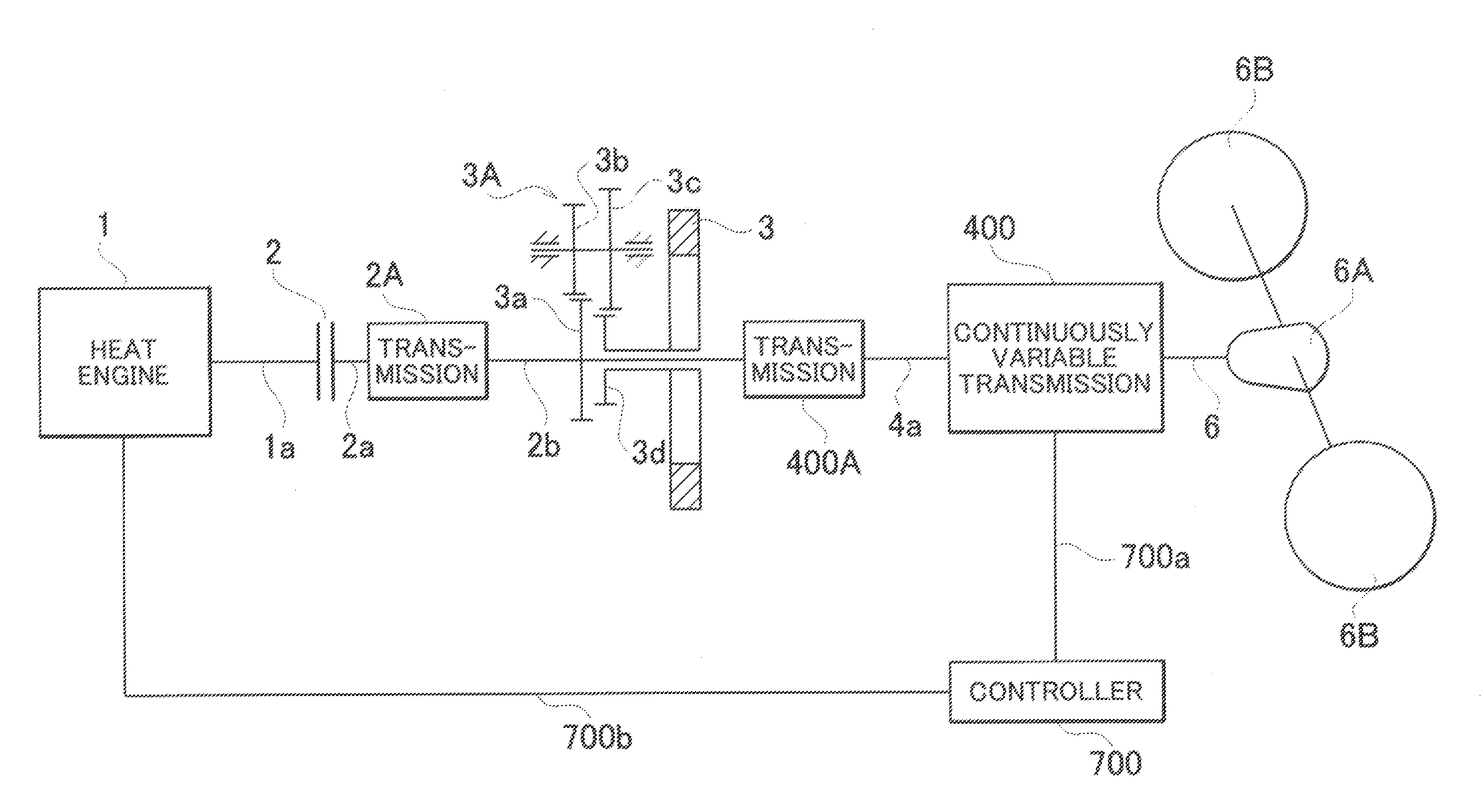
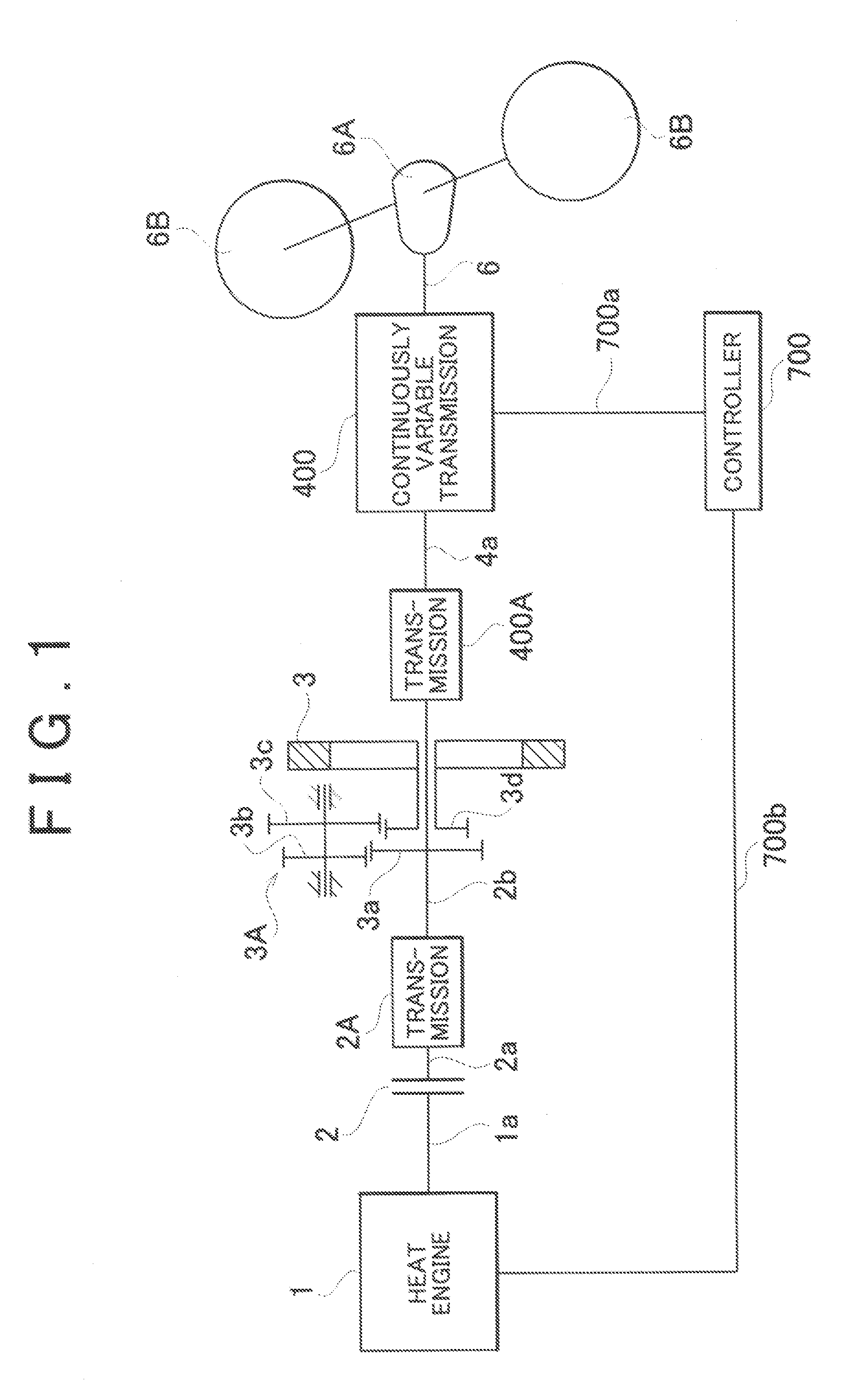
[the Continuously Variable Transmission 400 in FIG. 1]
[0226]FIG. 5 shows the first embodiment of the continuously variable transmission 400 in FIG. 1 with use of a numeral 401. The components having the same reference numerals as those in FIG. 1 are identical components. The mechanism of the continuously variable transmission 401 in FIG. 5 has been known in Miyao(jp2006-290330).
[0227]In FIG. 5, the numeral 7 depicts a control device. Control lines 7a, 7b, 7c, and 7d denoted by a single line include a plurality of power lines and control lines. A reference symbol Acc depicts a signal line for transmitting signals corresponding to an amount of depression of the accelerator pedal. The numeral 7A depicts a storage battery.
[0228]Transmissions 2A and 400A shown in FIG. 1 are omitted from the embodiment shown in FIG. 5 thereby to directly connect the drive shaft 2a to input shaft 4a.
[0229]In the continuously variable transmission 401, an outer rotor 4A for a generator-motor 4 is interlock...
second embodiment
[the Continuously Variable Transmission 400 in FIG. 1]
[0265]FIG. 6 shows the second embodiment of the continuously variable transmission 400 in FIG. 1 with use of a numeral 402. The components having the same reference numerals as those in FIG. 1 are identical components. Transmissions 2A and 400A shown in FIG. 1 are omitted from the embodiment shown in FIG. 6, in a manner similar to the embodiment shown in FIG. 5, thereby to directly connect the drive shaft 2a to input shaft 4a.
[0266]A continuously variable transmission 402 in FIG. 6 is a known continuously variable transmission of an input power split type disclosed in Miyao(jp2006-290330).
[0267]The continuously variable transmission 402 includes a differential gear 41. The differential gear 41 includes three shafts, a first of which is interlocked with an input shaft 4a, a second of which is interlocked with a reactive shaft 41f, and a third of which is interlocked with an outlet shaft 4b.
[0268]The contents of the differential ...
PUM
 Abstract
Description
Claims
Application Information