Eureka AIR delivers breakthrough ideas for toughest innovation challenges, trusted by R&D personnel around the world.

Device, an aggregate and a method for providing a gasified anesthetic agent

a technology of gasified anesthetic and aggregate, which is applied in the field of breathing apparatuses, can solve the problems of system not providing volume neutral delivery of gasified anesthetic agents, anesthetic vaporizers provided as integrated units in rather costly anesthesia workstations, etc., and achieve the effect of improving safety and avoiding delivery

Active Publication Date: 2012-02-09
MAQUET CRITICAL CARE
View PDF9 Cites 20 Cited by
  • Summary
  • Abstract
  • Description
  • Claims
  • Application Information

AI Technical Summary

Benefits of technology

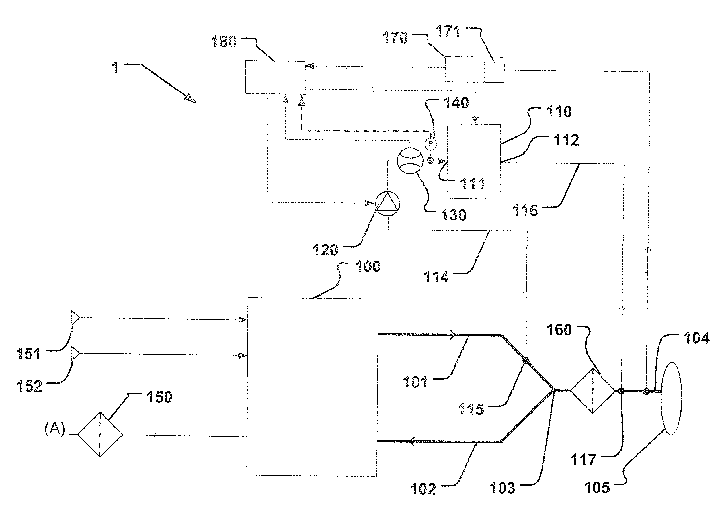
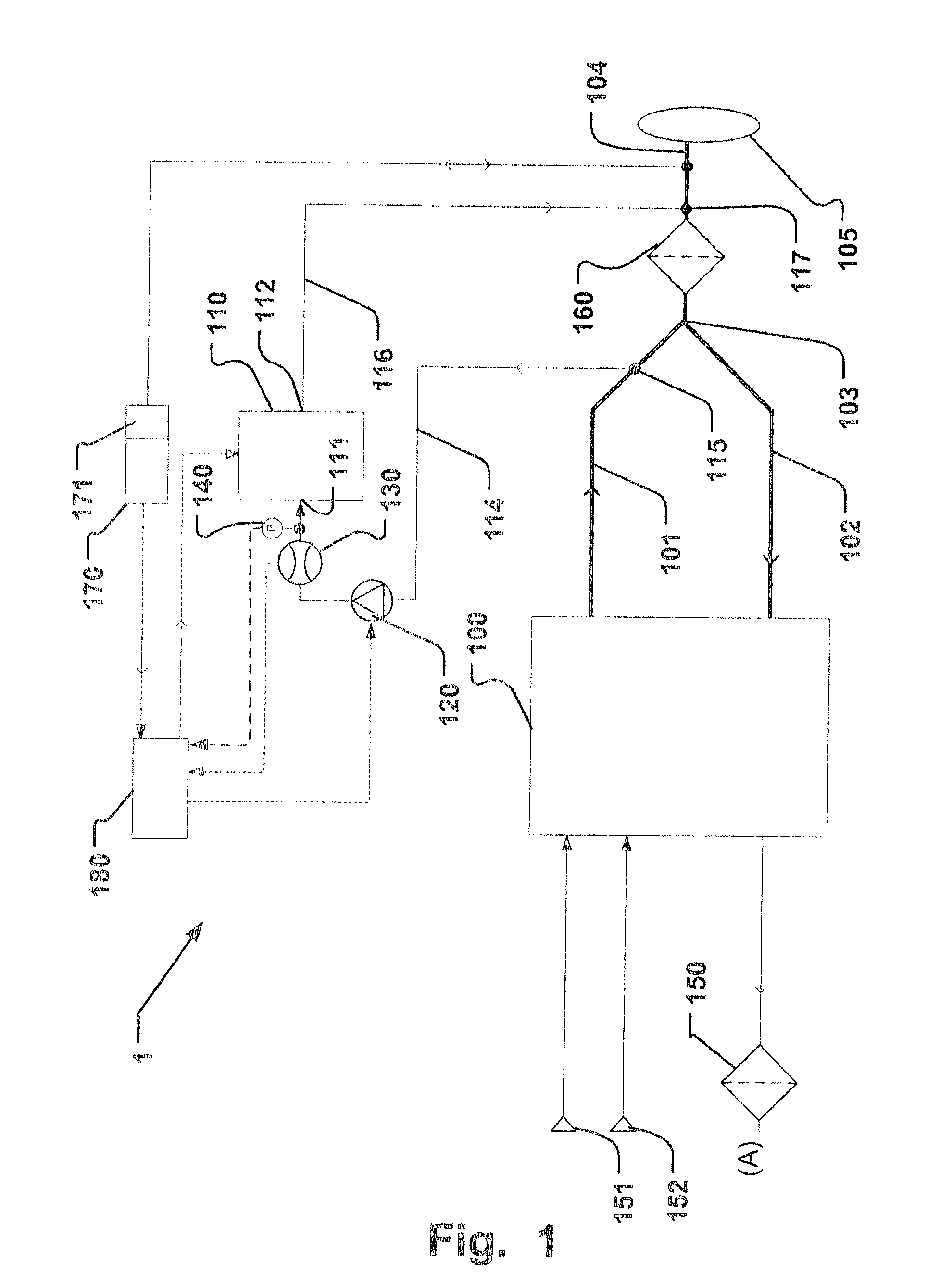
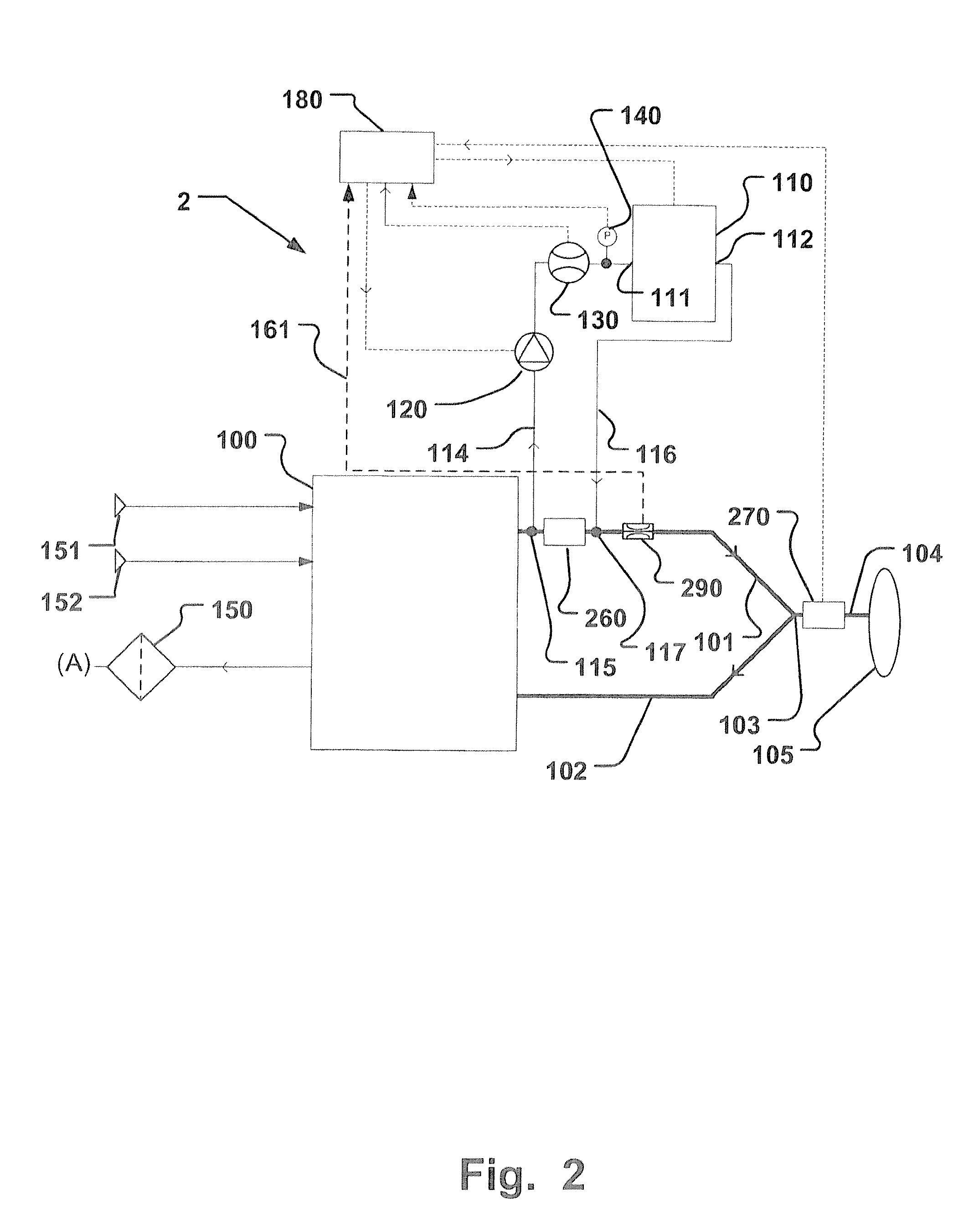
[0015]This volume neutrality is provided by an anesthetic gasifier unit adapted to supply gasified anesthetic agent with a carrier gas supply from a first point connected via a mainstream connection with a second point of a breathing circuit. The carrier gas is provided to the anesthetic gasifier unit in a sidestream flow of carrier gas. Hereinafter, the carrier gas with added gasified anesthetic agent is referenced to as “fresh gas”, using this wording, traditionally used in connection with circle breathing circuits, in the context of the present application. The anesthetic gasifier unit is further adapted to provide the gasified anesthetic agent to the second point in a volume neutral manner. In more detail, the total gas flow passing the first point into both the mainstream connection and the sidestream connection to the anesthetic gasifier unit is substantially equal to the recombined gas flow, enriched with the gasified anesthetic agent, at the second point. The volume of the gasified anesthetic agent in relation to the volume of the fresh gas, or the total volume of breathing gas delivered to the patient, is very low or negligible. Hence, no unnecessary or undesired volume of gas is added.
[0044]Embodiments of the invention provide for avoiding delivery of unvaporized liquid directly to a breathing circuit which is connected to a patient. Delivering liquid anesthetic to the patient could be a risk for the patient. Measurement of gasified anesthetic agent concentration and a feedback control thereof is made by means of units devised for measurement of gaseous component concentrations. In case a liquid portion of the anesthetic agent remains in the gas supplied to the patient, the measured agent concentration would be unreliable, and thus a risk for the patient may occur. Hence, embodiments of the invention prevent potentially dire consequences.

Problems solved by technology

However, anesthetic vaporizers are hitherto provided as integrated units in rather costly anesthesia workstations.
However, these systems were not providing a volume neutral delivery of gasified anesthetic agents, due to an additional fresh gas flow provided in addition to an inspiratory flow of gas from the ventilator.
Therefore, the gasified anesthetic agents are not provided in a way of volume neutral delivery with reference to the flow of breathing gas.
However, non-volume neutral delivery of anesthetic agent often results in a loss of anesthetic agent to the evac system due to the extra volume.
However such mainstream arrangements have some major disadvantages.
One issue is that liquid agent that is not fully vaporized may be present in the mainstream to the patient.
Droplets or aerosol of liquid anesthetic agent leads to several complications.
One complication is that gas analyzers may render less reliable measurement results for non gaseous components.
Thus, a feedback control of the agent concentration may be erroneous and the patient safety may be risked by too high administered anesthetic drug concentrations, i.e. the mainstream vaporizer of U.S. Pat. No. 6,155,255 may provide non-desired high doses.
Another issue is handling safety of the device of U.S. Pat. No. 6,155,255.
In this case, persons in the ambient environment, risk being subjected to the anesthetic agent, which might have dire health consequences.

Method used


Image

  • Device, an aggregate and a method for providing a gasified anesthetic agent
  • Device, an aggregate and a method for providing a gasified anesthetic agent
  • Device, an aggregate and a method for providing a gasified anesthetic agent

Examples


Embodiment Construction

[0053]Specific embodiments of the invention will now be described with reference to the accompanying drawings. This invention may, however, be embodied in many different forms and should not be construed as limited to the embodiments set forth herein; rather, these embodiments are provided so that this disclosure will be thorough and complete, and will fully convey the scope of the invention to those skilled in the art. The terminology used in the detailed description of the embodiments illustrated in the accompanying drawings is not intended to be limiting of the invention. In the drawings, like numbers refer to like elements.

[0054]The following description describes embodiments applicable to a breathing apparatus and in particular to a respiratory ventilator in use connected to sources of pressurized gas. However, it will be appreciated that the invention is not limited to this application but may be applied to many other breathing apparatuses, including for example fan driven bre...


PUM


Abstract

A respiratory anesthetic aggregate devised for coupling to a breathing apparatus has an anesthetic gasifier unit that has a breathing gas input port connected to a first point in an inspiratory patient gas delivery path of a breathing apparatus, and a fresh gas output port connected to a second point in the patient gas delivery path downstream the first point. The inspiratory patient gas delivery path is connected via a mainstream connection between the first and second point. Thereby the anesthetic gasifier unit is connected in a sidestream configuration to the patient gas delivery path for adding the gasified anesthetic agent in a desired concentration to the patient gas delivery path at the second point. The When aggregate is coupled to a breathing apparatus, a substantially volume neutral delivery of anesthetic agent is provided a to the breathing apparatus.

Description

BACKGROUND OF THE INVENTION[0001]1. Field of the Invention[0002]This invention pertains in general to the field of breathing apparatuses. More particularly the invention relates to a device, aggregate and / or method for providing a gasified anesthetic agent by means of a breathing apparatus.[0003]2. Description of the Prior Art[0004]Certain anesthetic vaporizers for liquid anesthetic agents are known from the prior art.[0005]For instance, in U.S. Pat. No. 6,230,666 an anesthetic vaporizer is disclosed for an anesthesia machine.[0006]However, anesthetic vaporizers are hitherto provided as integrated units in rather costly anesthesia workstations. In addition, there have been previous systems based on intensive care ventilators with added anesthesia capability, such as the Siemens-Elema Servo Ventilator 900C. However, these systems were not providing a volume neutral delivery of gasified anesthetic agents, due to an additional fresh gas flow provided in addition to an inspiratory flow ...

Claims


Application Information

Patent Timeline
Patent Type & Authority Applications(United States)
IPC IPC(8): A61M16/01A61M16/10
CPCA61M16/0078A61M16/009A61M2202/048A61M16/1045A61M16/18A61M16/01A61M16/1055A61M16/0093
Inventor LONCAR, MARIOWALLIN, MATSAHLMEN, CHRISTER
Owner MAQUET CRITICAL CARE
Why Eureka
Eureka Blog
Learn More