Device and method for converting incident radiation into electrical energy using an upconversion photoluminescent solar concentrator

a technology of photoluminescent solar concentrator and incident radiation, which is applied in the direction of luminescent dosimeter, optical radiation measurement, fluorescence/phosphorescence, etc., can solve the problems of large solar spectrum that cannot be used by conventional concentrators for generating electricity, and requires inefficient solar tracking methods, etc., to achieve the probability of reabsorption of emitted photons and higher energy

Inactive Publication Date: 2012-02-09
BRUER GARRETT
View PDF5 Cites 21 Cited by
  • Summary
  • Abstract
  • Description
  • Claims
  • Application Information

AI Technical Summary

Benefits of technology

[0036]In another embodiment, the method also includes absorbing a second incident radiation with a second upconversion chromophore, wherein the second incident radiation has higher energy than the incident radiation, emitting a second emitted photon from the second upconversion chromophore, wherein the second emitted photon has higher energy than the second incident radiation, directing the second emitted photon from the second upconversion chromophore to the photovoltaic device using a second waveguide, and the photovoltaic device absorbing the second emitted photon and converting to electrical energy.
[0037]In another embodiment, the method also includes absorbing a third incident radiation with a third upconversion chromophore, wherein the third incident radiation has higher energy than the incident radiation, emitting a third emitted photon from the third upconversion chromophore, wherein the third emitted photon has higher energy than the third incident radiation, directing the third emitted photon from the third upconversion chromophore to a third photovoltaic device using a third waveguide, and the third photovoltaic device absorbing the third emitted photon and converting to electrical energy.
[0038]In another embodiment, the emitted photon and the second emitted photon have the same energy. In another embodiment, the second emitted photon has higher energy than the emitted photon.
[0039]In an embodiment, the upconversion photoluminescent solar concentrator device includes a first waveguide including a first waveguide medium, a chromophore layer provided on a surface of the first waveguide, the chromophore layer including a plurality of upconversion chromophores in contact with the first waveguide medium. A second waveguide is provided above the chromophore layer, wherein the second waveguide includes a second waveguide medium, the plurality of upconversion chromophores in contact with the second waveguide medium. A photovoltaic device provided at an end side of the first waveguide and the second waveguide. The first waveguide is configured to direct an emitted photon from one of the plurality of the upconversion chromophores entering the first waveguide towards a photovoltaic device. The second waveguide is configured to direct the emitted photon from one of the plurality of the upconversion chromophores entering the second waveguide towards the photovoltaic device. In an embodiment, the first and/or the second waveguide medium is a liquid. In an embodiment, the first and/or the second waveguide has a rod-like shape axially and a geometric cross-section. In an embodiment, the first and/or the second waveguide medium is one selected from the group consisting of an amorphous silicon dioxide, a silicon dioxide, a clear plastic, a clear liquid, a glass, an organic glass, a glass doped with a Group II-VI semiconductor and acrylic plastic. In an embodiment, the upconversion chromophore is an H-aggregate. In an embodiment, the upconversion chromophore is a rare-earth ion. In an embodiment, an antireflection coating is provided on a side of the first and/or the second waveguide. The antireflection coating may be provided between the waveguide and the chromophore layer. A taper may be provided on a side of the waveguide with the antireflection coating being provided therebetween. In an embodiment, a refractive in

Problems solved by technology

Conventional light concentrating devices and techniques utilize the direct component of radiation, thus requiring inefficient methods like solar tracking.
Because conventional concentrators can access only the UV spectrum, conventional concentrators use only a limited portion of the

Method used


Image

  • Device and method for converting incident radiation into electrical energy using an upconversion photoluminescent solar concentrator
  • Device and method for converting incident radiation into electrical energy using an upconversion photoluminescent solar concentrator
  • Device and method for converting incident radiation into electrical energy using an upconversion photoluminescent solar concentrator

Examples


Embodiment Construction

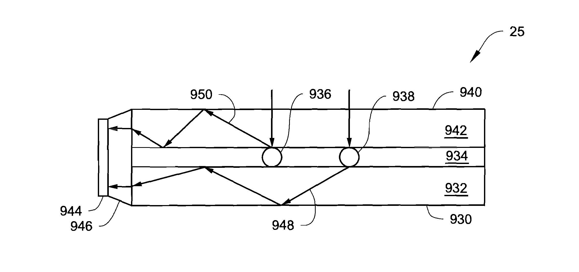
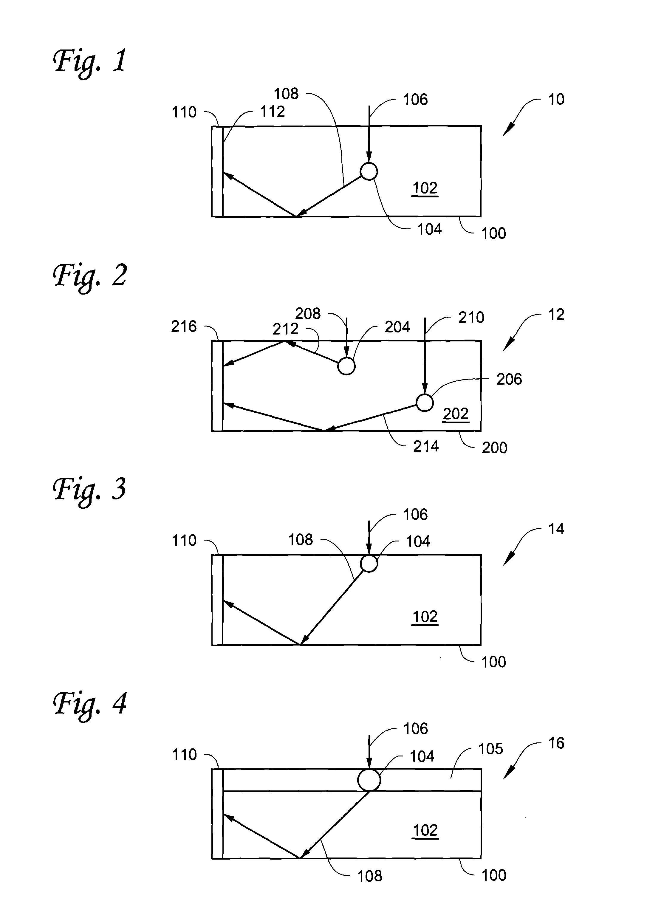
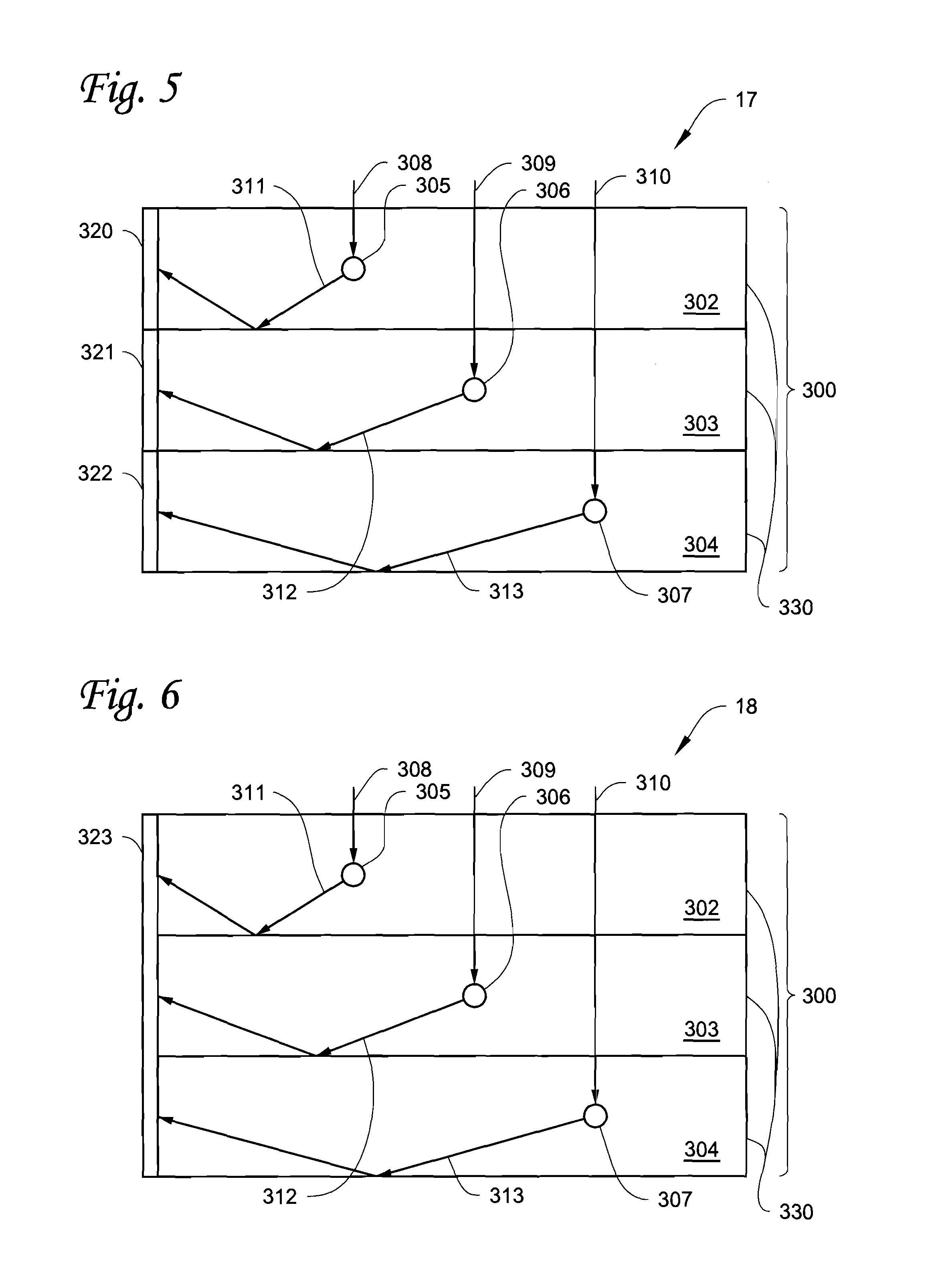
[0060]A method for converting incident radiation into electrical energy includes absorbing the incident radiation with an upconversion chromophore, emitting an emitted photon from the upconversion chromophore, wherein the emitted photon has higher energy than the incident radiation, directing the emitted photon from the upconversion chromophore to a photovoltaic device using a waveguide, and the photovoltaic device absorbing the emitted photon and converting to electrical energy. The method may also include absorbing a second incident radiation with a second upconversion chromophore, wherein the second incident radiation has higher energy than the incident radiation, emitting a second emitted photon from the second upconversion chromophore, wherein the second emitted photon has higher energy than the second incident radiation, directing the second emitted photon from the second upconversion chromophore to the photovoltaic device using a second waveguide, and the photovoltaic device ...


PUM


Abstract

Device and method for converting incident radiation into electrical energy using an upconversion photoluminescent solar concentrator is disclosed. An upconversion photoluminescent solar concentrator device includes a waveguide. The waveguide has a waveguide medium. An upconversion chromophore is in contact with the waveguide medium. The upconversion chromophore is configured to absorb an incident photon. The upconversion chromophore is also configured to emit an emitted photon. The emitted photon has higher energy than the incident photon. A photovoltaic device absorbs the emitted photon, generating electricity.

Description

CROSS-REFERENCE TO RELATED APPLICATIONS[0001]This application is a continuation-in-part of the PCT International Application No. PCT / US2010 / 033400 filed on May 3, 2010, the entire contents of which are hereby incorporated by reference.[0002]This application claims priority of U.S. Provisional Application No. 61 / 174,494 filed on May 1, 2009, the entire contents of which are hereby incorporated by reference.FIELD[0003]This description relates generally to an upconversion photoluminescent solar concentrator and a photovoltaic device connected to the upconversion photoluminescent solar concentrator.BACKGROUND[0004]Light concentrators can considerably reduce the cost of electricity from photovoltaic (PV) cells. Conventional light concentrating devices and techniques utilize the direct component of radiation, thus requiring inefficient methods like solar tracking.[0005]Light concentrating device for concentrating solar light using a fluorescent collector is known. The fluorescent collecto...

Claims


Application Information

Patent Timeline
IPC IPC(8): H01L31/052H01L31/0232G01N21/64
CPCY02E10/52H01L31/055
Inventor BRUER, GARRETT
Owner BRUER GARRETT
Why Eureka
Try Eureka