Spindle motor and storage disk drive

Inactive Publication Date: 2012-02-09
NIDEC CORP
View PDF1 Cites 19 Cited by
  • Summary
  • Abstract
  • Description
  • Claims
  • Application Information

AI Technical Summary

Benefits of technology

[0011]In the motor according to a preferred embodiment of the present invention, it is possible to achieve a reduction in a difference in pressure between the upper seal portion and t

Problems solved by technology

Because of this, it is necessary to provide a complica

Method used


Image

  • Spindle motor and storage disk drive
  • Spindle motor and storage disk drive
  • Spindle motor and storage disk drive

Examples


Embodiment Construction

[0033]It is assumed herein that an upper side and a lower side in a direction parallel or substantially parallel to a central axis of a motor are referred to as an “upper side” and a “lower side”, respectively. Note that the terms “vertical direction”, “upper side”, “lower side”, and the like as used herein are not meant to indicate relative positions or directions of different members or portions when actually installed in a device. Also note that directions parallel to or substantially parallel to the central axis are referred to by the term “axial direction”, “axial”, or “axially”, that directions radiating from the central axis are simply referred to by the term “radial direction”, “radial”, or “radially”, and that a circumferential direction about the central axis is simply referred to by the term “circumferential direction”, “circumferential”, or “circumferentially”.

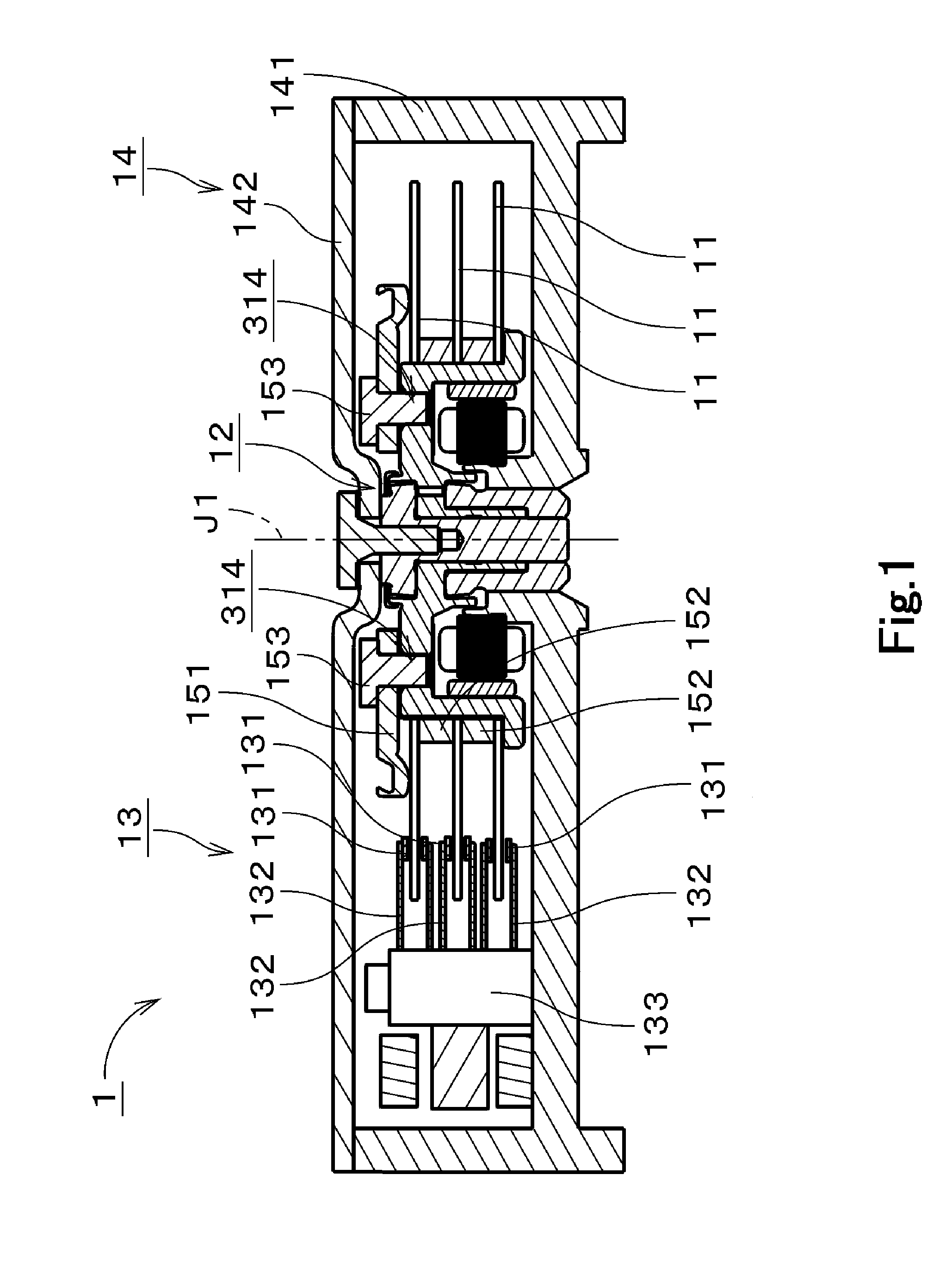
[0034]FIG. 1 is a vertical cross-sectional view of a storage disk drive 1 including a spindle motor (hereinafter...


PUM


Abstract

A spindle motor includes a stationary portion and a rotating portion. The stationary portion preferably includes a shaft portion, an upper thrust portion, and an outer tubular portion. The rotating portion preferably includes an inner tubular portion, a flange portion, an upper hub annular portion, and a lower hub annular portion. The flange portion includes a communicating hole. An upper surface of a lubricating oil is located in a fifth gap defined between an upper thrust portion and an upper hub annular portion, while a lower surface of the lubricating oil is located in a sixth gap defined between an outer tubular portion and a lower hub annular portion. The communicating hole and a space extending from the fifth gap to the sixth gap through a fourth gap, a first gap, a second gap, and a third gap are continuously filled with the lubricating oil.

Description

BACKGROUND OF THE INVENTION[0001]1. Field of the Invention[0002]The present invention relates to a spindle motor and mores specifically to a spindle motor for use in a storage disk drive.[0003]2. Description of the Related Art[0004]Motors including a bearing mechanism using fluid dynamic pressure have often been used in storage disk drives. An example of a known dynamic pressure fluid bearing apparatus in a spindle motor is disclosed in JP-A 2007-162759. This spindle motor includes a shaft body and a tubular sleeve body inside which the shaft body is inserted. The shaft body is fixed to a base plate of the motor. The sleeve body is fixed to a rotor of the motor. The shaft body is provided with a first thrust flange and a second thrust flange. The first thrust flange and second thrust flange are both annular and are arranged on an upper and a lower side of the sleeve body, respectively. In the dynamic pressure fluid bearing apparatus, a radial bearing portion is defined between the s...

Claims


Application Information

Patent Timeline
IPC IPC(8): G11B17/02H02K7/08
CPCH02K7/085F16C17/107G11B19/20
Inventor MIZUKAMI, JUNYAOE, TAKAYUKISEKII, YOICHISABASHI, NAOKINISHIMURA, HIDEKITAMAOKA, TAKEHITOYAMAMOTO, TAKASHI
Owner NIDEC CORP
Why Eureka
Try Eureka