Rotary flexure bearing

a bearing and flexure technology, applied in the direction of vehicles/pulleys, mechanical devices, couplings, etc., can solve the problems of increasing the coaxial error between the desired and actual axis of rotation, and catastrophic failure, and achieve the effect of eliminating the need for user-designed mounting hardwar

Active Publication Date: 2012-02-09
VALOIS MICHAEL
View PDF24 Cites 15 Cited by
  • Summary
  • Abstract
  • Description
  • Claims
  • Application Information

AI Technical Summary

Benefits of technology

[0011]1) The proposed rotary flexure bearing has integrated mounting flanges. In addition to a screw-hole pattern, centering and clocking features are machined into the mounting flanges during flexure fabrication. This makes the flanges concentric with the axis of rotation and eliminates the need for user designed mounting hardware.

Problems solved by technology

Motivation for the proposed rotary flexure bearing is partially based on the limited availability of high quality rotary flexure bearings.
1) Since they do not have integrated mounting features, the engineer must design and build custom hardware to attach the flex-pivot to the mechanism. The manufacturing and assembly tolerances associated with this additional hardware will increase the coaxial error between the desired and actual axis of rotation.
2) The flex-pivots are made of multiple pieces of 400 series stainless steel that are brazed together. This choice of material and fabrication technique favors mass production but limits application to environments benign enough for 400 series stainless steel, the brazing material, and the galvanic potential of the stainless steel-to-brazing material interface. Failure of any brazed joint will result in catastrophic failure.

Method used


Image

  • Rotary flexure bearing
  • Rotary flexure bearing
  • Rotary flexure bearing

Examples


Embodiment Construction

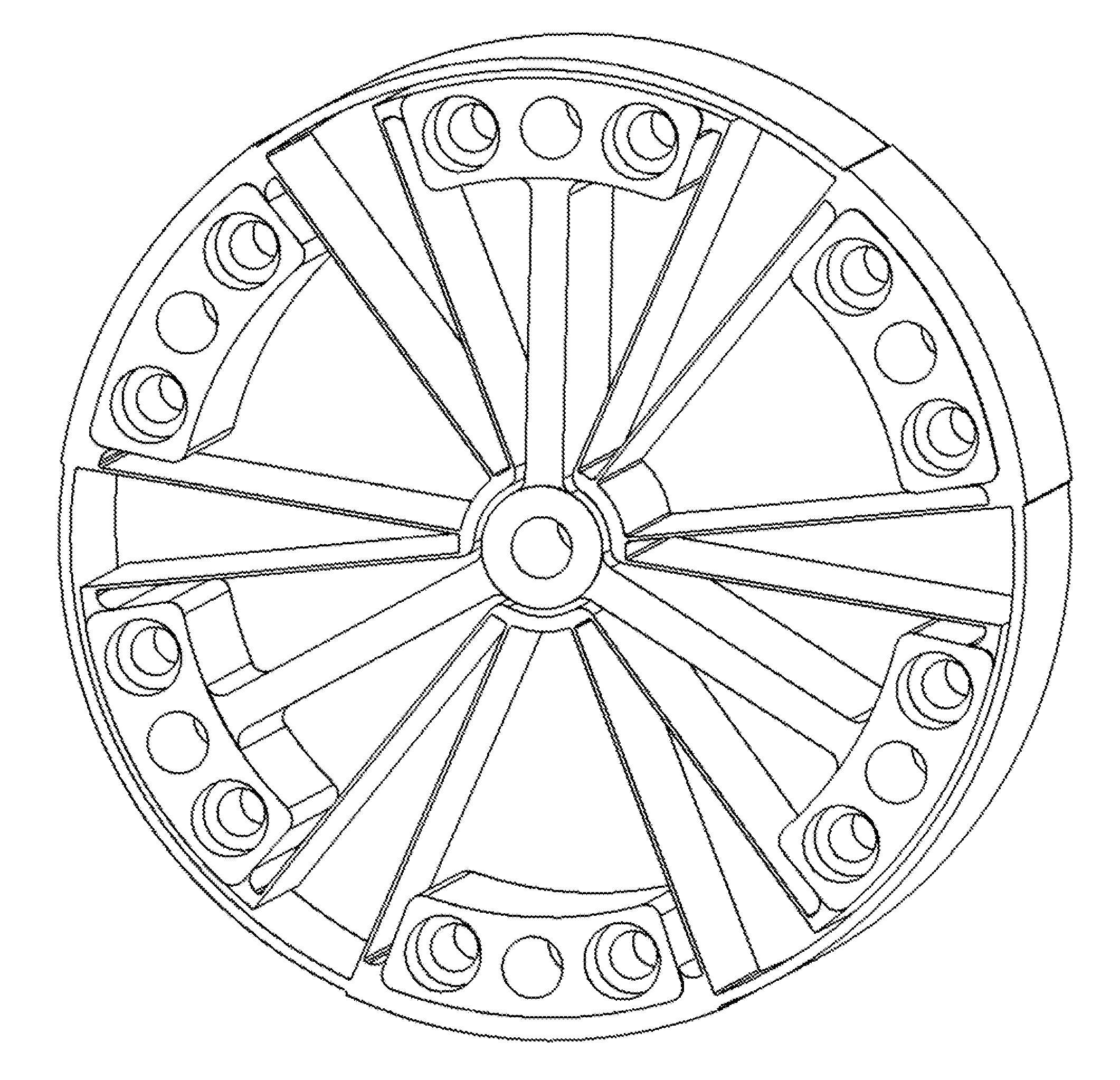
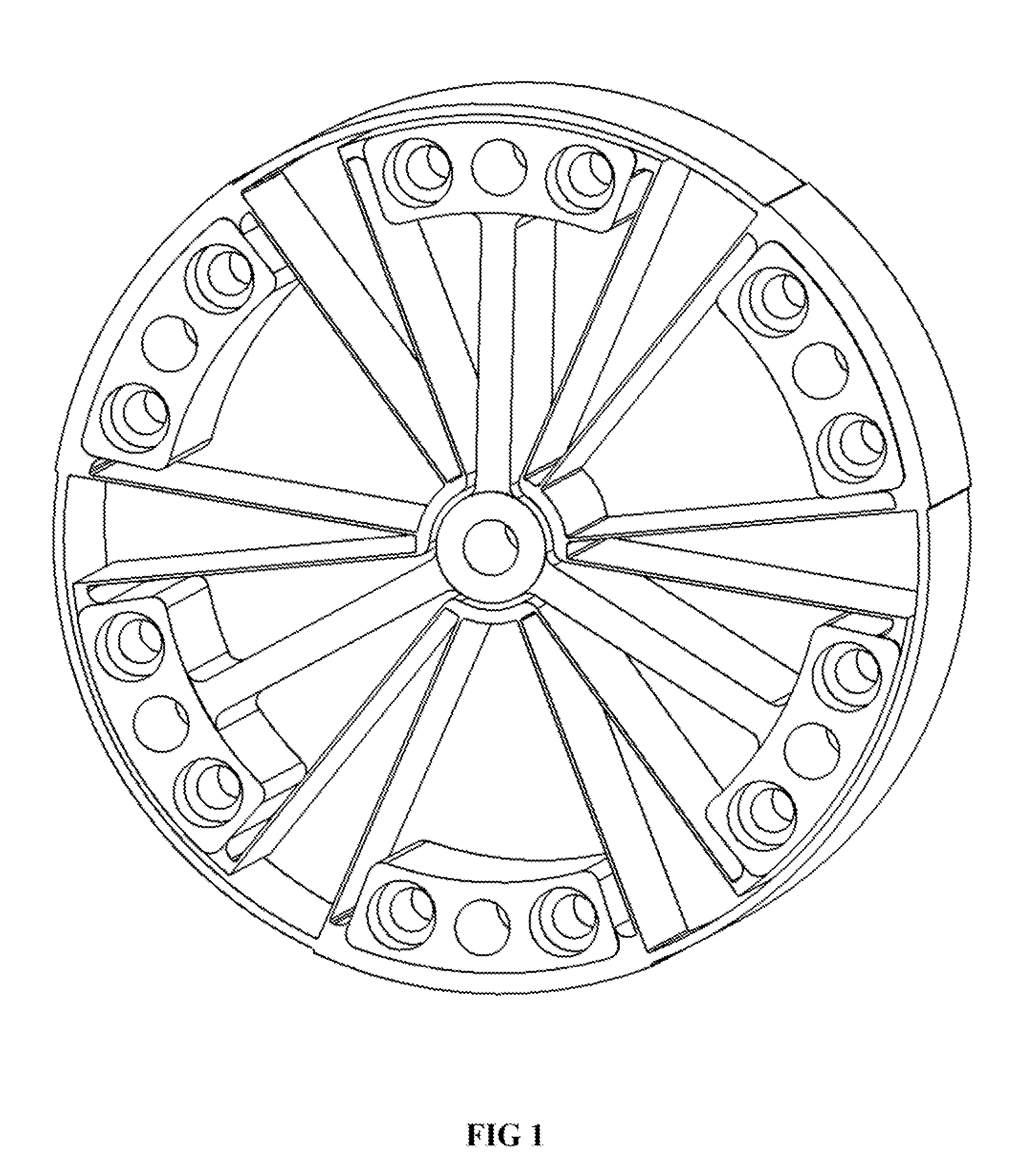
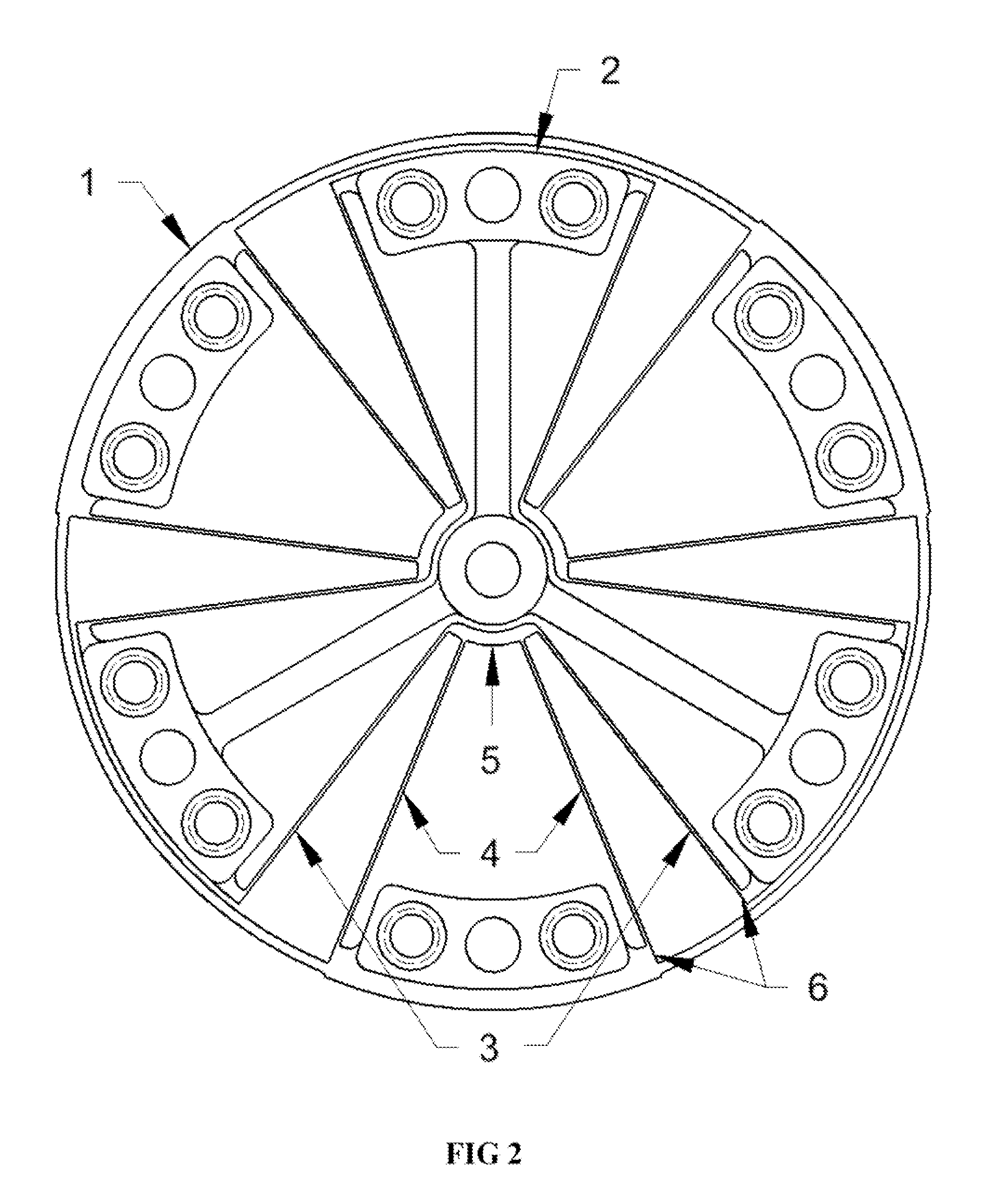
[0023]The arrangement of three compound flexure stages can be seen in FIG. 2. Each compound stage has four blade flexures. All twelve blade flexures are the same thickness, width, and length, therefore have the same stiffness as well. The two inner blade flexures 4 in each compound stage connect the outer hub l of the rotary flexure bearing to the regulator link 5. The two outer blade flexures 3 in each compound stage connect the three-legged inner hub 2 to the regulator link 5. Each of the three compound stages is defined by one inner blade flexure stage and one outer blade flexure stage that are nested together. The inner blade flexure stage consists of the inner blade flexures and the regulator link while the outer blade flexure stage is defined by the outer blade flexures and regulator link. The regulator link is shared by both the inner and outer blade flexure stages and allows the two stages to work together as a complete compound flexure stage. The inner blade flexure stage h...


PUM


Abstract

This rotary flexure bearing is a monolithic structure with inner and outer hubs connected by unique rotary compound flexure stages. These rotary compound flexure stages provide the angular compliance required for bearing rotation as well as compliance for flexure foreshortening while holding a constant axis of rotation with great precision over the entire range of motion. This design offers large angular displacement, low operating stress, low operating torque, and high stiffness in the five noncompliant degrees of freedom. The rotary flexure bearing described herein has applications in precision mechanics, particularly opto-mechanics. Specific applications include but are not limited to wafer and reticle alignment stages used in microlithography systems, mirror pointing and scanning mechanisms used in tactical and spaceborne systems, as well as flip-in mechanisms used in multiple field of view optical systems.

Description

CROSS-REFERENCE TO RELATED APPLICATIONS[0001]Not ApplicableFEDERALLY SPONSORED RESEARCH OR DEVELOPMENT[0002]Not ApplicableREFERENCE TO SEQUENCE LISTING[0003]Not ApplicableBACKGROUND OF THE INVENTION[0004]This invention generally relates to a flexure based rotary guide bearing. Flexures have been used successfully in simple and inexpensive as well as complicated and expensive motion systems for centuries. Since they operate by bending, not rolling or sliding, flexures have the inherent advantage of friction-free motion. This key feature allows engineers to build positioning systems with nearly unlimited precision and accuracy. They are also easy to design and fabricate. However, even with these desirable attributes there are very few flexure based bearings available commercially. Therefore, it is common practice for an engineer to design custom flexure systems while developing a new mechanism. The rotary flexure bearing described herein is particularly well suited for integration int...

Claims


Application Information

Patent Timeline
Patent Type & Authority Applications(United States)
IPC IPC(8): F16C11/12
CPCF16C11/12Y10T403/54Y10T403/451Y10T403/10
Inventor VALOIS, MICHAEL
Owner VALOIS MICHAEL
Why Eureka
Try Eureka