Data center and computer storing rack therefor

a technology for computer storage and data centers, which is applied in the direction of casings/cabinets/drawers, casings/cabinets/drawers, instruments, etc., can solve the problems of increasing the number of computers such as servers, and the electric power consumption of data centers has been rising, so as to reduce the burden on the environment, reduce the cost, and the effect of reducing the energy consumed by the data center

Inactive Publication Date: 2012-02-09
OKADA RYOSUKE +1
View PDF28 Cites 5 Cited by
  • Summary
  • Abstract
  • Description
  • Claims
  • Application Information

AI Technical Summary

Benefits of technology

[0005]In consideration of these factors, the present invention seeks to solve the problem of providing a data center that can allow computers such as servers to operate in a stable manner and that can greatly reduce energy consumption during operation, and of providing a rack for computer storage used in such a data center.
[0013]With the data center according to the present invention, external air that has been sucked into the intake area passes through the rack for computer storage and flows to the exhaust area, and at this time is able to abstract the heat generated by one or more computers that are stored in said rack. Since the air that has been warmed by the computers is exhausted to the exterior, accordingly the necessity for cooling this air itself is utterly nil or remarkably low. Since it is possible to build a data center that operates according to this kind of air flow control, accordingly the energy consumed by the data center is remarkably reduced, so that it may be anticipated that great cost reductions and great lessening of the burden on the environment will result. According to the present invention, there is no requirement for any complicated constructional features such as a double floor or the like for air conditioning, as was the case with a prior art data center. And the rack for computer storage according to the present invention is appropriate for application to the data center described above, since it is capable of flowing air with good efficiency to the interior of a computer that is stored in it.
[0014]Since, according to a preferred aspect of the present invention, it is possible for an operator to come and go between the intake area and the exhaust area via the airtight chamber, accordingly the working efficiency within the data center is enhanced. And, according to another preferred aspect, it is possible to increase the number of intake areas that are provided within the data center, so that it is possible to increase the number of computers that can be stored and operated. Furthermore, according to another preferred aspect, according to requirements, it is possible to take the warm air that has been exhausted back into the intake area or areas. Due to this, when the temperature is low such as at night-time or during winter or the like, it is possible to suppress overcooling of the computers and to keep the data center warm. Moreover, according to another preferred aspect, it is possible to suppress changes of temperature within the data center by controlling the air flow by utilizing feedback of a signal from a temperature sensor, and by taking in a portion of the air that has been warmed and exhausted back into the intake area.

Problems solved by technology

For some time the electrical power consumption of data centers has been rising along with the increase in the numbers of computers such as servers.

Method used


Image

  • Data center and computer storing rack therefor
  • Data center and computer storing rack therefor
  • Data center and computer storing rack therefor

Examples


examples

[0039]While the present invention will now be explained in greater detail in the following with reference to concrete embodiments thereof, the present invention should not be considered as being limited to those embodiments.

example # 1

Example #1

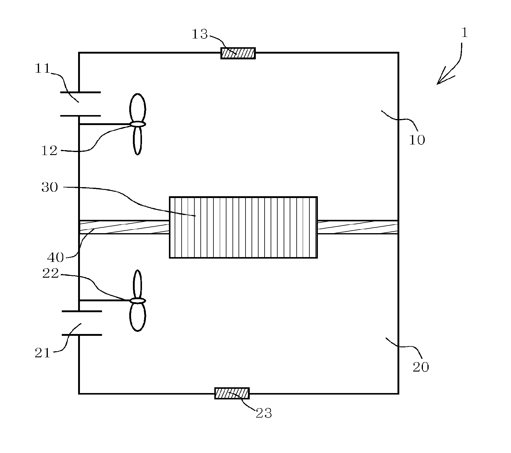
[0040]Servers were operated in an actual data center as described below. A schematic plan view of this data center is as shown in FIG. 1 and referred to above. However, in consideration of ease of working upon the servers, the intake area 10 was made larger than the exhaust area 20. In concrete terms, the intake area 10 was made of dimensions 4.5 m×2.1 m, while the exhaust area 20 was made of dimensions 4.5 m×1.0 m. A hood was provided to the intake aperture 11, and three fans 12 were installed for intake of air. The capability of these fans was as follows: pressure blades 40 cm; 1700 m3 / h; 100 Pa; single phase 100 V; 135 W. And a hood was provided to the exhaust aperture 21, and three fans 22 were installed for exhaust of air. For these exhaust fans, similar fans to the intake fans described above were used. These hoods and fans served the roles of intake apparatus, exhaust apparatus, and air flow control means.

[0041]As the dividing wall 40, a fireproof wall of 12 cm thic...

example # 2

Example #2

[0045]The servers were operated in the same data center as in the case of Example #1 on another day (2 Sep. 2009). On that day the external air was at 24° C. (the highest temperature).

[0046]With this embodiment, the servers were operated in the state in which a load was imposed upon the CPUs and the HDDs. In order to impose a load upon the CPUs, a sign function was executed a million times. When this sort of load is imposed without any particular cooling measures being instituted, normally, the CPUs attain temperatures of as much as 50° C. In this Example, the air flow was controlled by operating the fans 12 and 22. The temperatures of the various parts at this time were as follows:

TemperatureTemperatureTemperature ofTemperature ofTimeof CPUsof HDDsrack intake siderack exhaust side12:0038° C.30° C. 23.1° C.27.04° C.14:0040° C.31° C.23.58° C.27.68° C.16:0040° C.31° C.23.58° C.27.68° C.18:0039° C.30° C.23.26° C.27.36° C.20:0038° C.30° C.22.78° C.26.88° C.

[0047]As described a...


PUM


Abstract

The problem for the present invention is to provide a data center that can allow computers such as servers or the like to be operated stably and that can greatly reduce energy consumption during operation, and a rack for storage of computers to be used therein. According to the present invention, a data center 1 is provided as a building for installation and operation of computers, and includes an intake area 10 provided with an intake device that sucks external air into the building, an exhaust area 20 provided with an exhaust device that discharges air to the exterior of the building, a dividing wall 40 that separates the intake area 10 from the exhaust area 20, a rack 30 for computer storage installed so as to pierce through a portion of the dividing wall 40, and an air flow control means that controls air flow so that air in the intake area 10 passes through the rack for computer storage 30 and flows to the exhaust area 20.

Description

TECHNICAL FIELD[0001]The present invention relates to a data center which is a building for installation and operation of computers, and to a rack for storage of computers that are used therein.BACKGROUND ART[0002]For some time the electrical power consumption of data centers has been rising along with the increase in the numbers of computers such as servers. Recently, along with the raising of consciousness about environmental problems, attention has focused upon economization of energy in data centers as being a very important subject. Due to this, in recent design of data centers, there has been a demand for keeping down the amount of electrical power used, and also for managing generation of heat and so on.[0003]With a typical data center, as described in JP 2009-63226 A, in order to eliminate the heat generated by the computers, a construction is adopted in which cool air is drawn in from below the floor, hot air is exhausted from the ceiling, and so on. To put it in another ma...

Claims


Application Information

Patent Timeline
Patent Type & Authority Applications(United States)
IPC IPC(8): H05K5/02
CPCG06F1/206Y02D10/16H05K7/20745H05K7/20736Y02D10/00G06F1/20
Inventor OKADA, RYOSUKEOTSUKA, RYUICHI
Owner OKADA RYOSUKE
Why Eureka
Try Eureka