Tracheal Stent With Longitudinal Ribs to Minimize Stent Movement, Coughing and Halitosis

a tracheal stent and longitudinal rib technology, applied in the field of tracheal stent with longitudinal ribs to minimize stent movement, coughing and halitosis, can solve the problems of displacement of the stent within the trachea, excessive coughing in the respiratory tract, and buildup of phlegm

Inactive Publication Date: 2012-02-09
BOSTON SCI SCIMED INC
View PDF10 Cites 76 Cited by
  • Summary
  • Abstract
  • Description
  • Claims
  • Application Information

AI Technical Summary

Benefits of technology

[0006]In at least one embodiment, a cleat set is formed with four cleats. The first cleat is circumferentially adjacent to the second cleat, and the third cleat is circumferentially adjacent to the fourth cleat. The first cleat is axially spaced apart from the third cleat, and the second cleat is axially spaced apart from the fourth cleat. The first cleat is symmetrical to the second cleat and the third cleat; the second cleat is symmetrical to the first cleat and the fourth cleat; the third cleat is symmetrical to the first cleat and the fourth cleat; and the fourth cleat is symmetrical to the third cleat and the second cleat. The first cleat is parallel to the fourth cleat and the second cleat is parallel to the third cleat. The cleat set provides the counteracting forces required to hold the stent in position in the trachea.

Problems solved by technology

However, these stents may be impermeable or may entirely cover the inside of the trachea, including the cilia that move mucous and inhaled particles upward toward the epiglottis, where the mucous or particles are either swallowed or coughed up.
When covered, the cilia are unable to help remove the mucous and other particles from the respiratory system, which can result in the build up of phlegm, halitosis, and excessive coughing in the respiratory tract.
Such coughing may also cause displacement of the stent within the trachea.

Method used


Image

  • Tracheal Stent With Longitudinal Ribs to Minimize Stent Movement, Coughing and Halitosis
  • Tracheal Stent With Longitudinal Ribs to Minimize Stent Movement, Coughing and Halitosis
  • Tracheal Stent With Longitudinal Ribs to Minimize Stent Movement, Coughing and Halitosis

Examples


Embodiment Construction

[0035]While this invention may be embodied in many different forms, there are described in detail herein specific preferred embodiments of the invention. This description is an exemplification of the principles of the invention and is not intended to limit the invention to the particular embodiments illustrated.

[0036]For the purposes of this disclosure, like reference numerals in the figures shall refer to like features unless otherwise indicated.

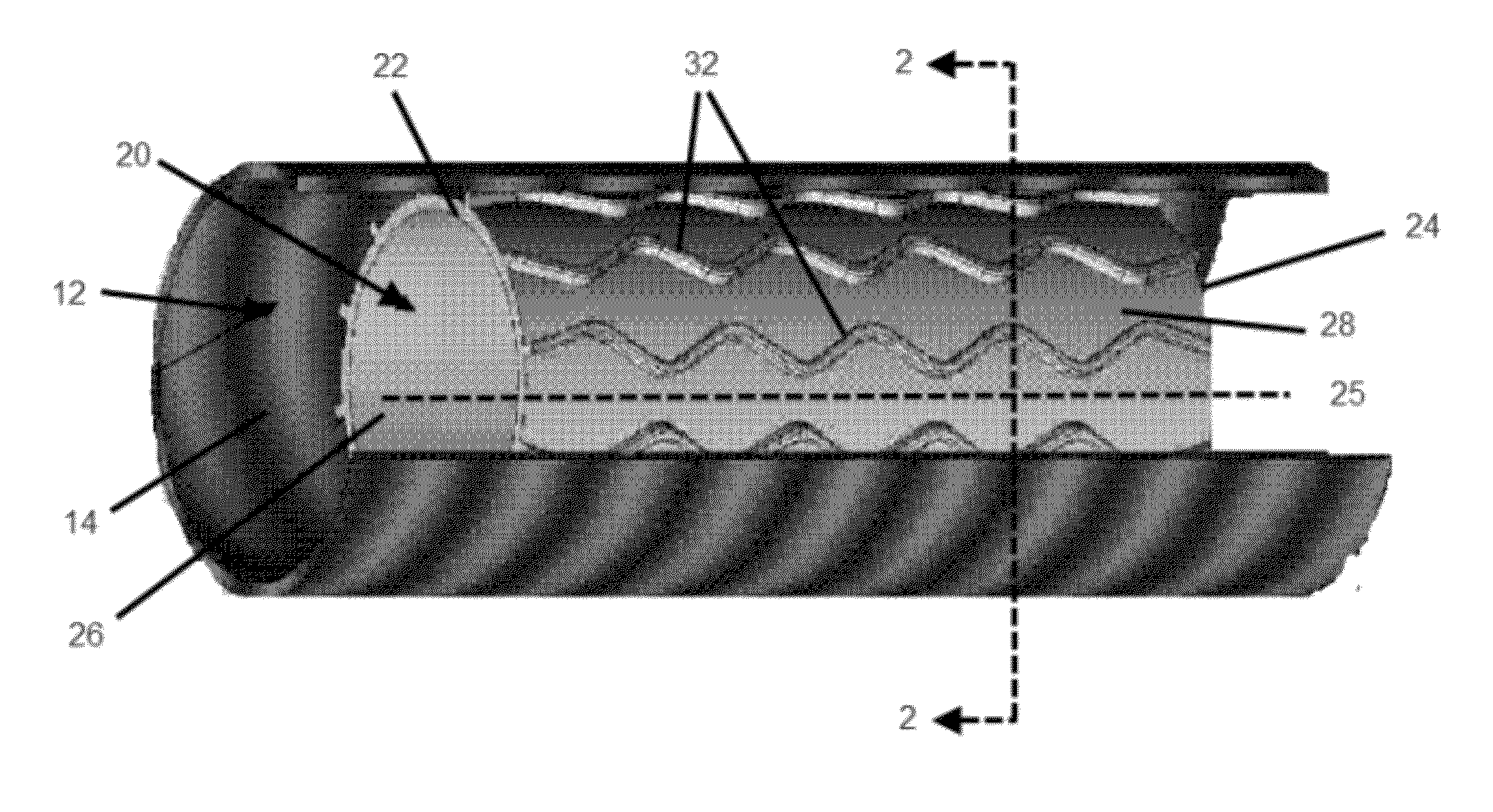
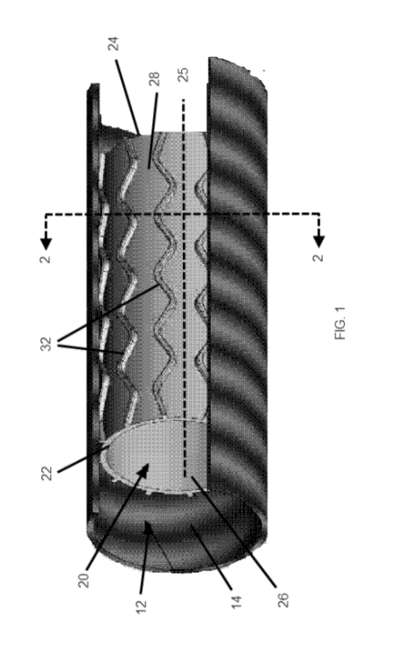
[0037]An embodiment of a stent of the present invention deployed in a trachea is shown in FIG. 1. The trachea 12 has an inner surface 14. The inner surface 14 forms the lumen of the trachea 12, and a plurality of cilia (not shown) line the inner surface 14. Stent 20 is shown deployed in the lumen of the trachea 12. In at least one embodiment, stent 20 is an expandable tubular member 21 that has a proximal end 22, a distal end 24, a longitudinal axis 25 extending through the proximal end 22 and the distal end 24, an inner surface 26, and an ...


PUM


Abstract

A tracheal stent is an expandable tubular member having a proximal end, a distal end, an inner surface, and an outer surface. Circumferentially adjacent surface protrusions extend outwardly from the outer surface of the expandable tubular member. These surface protrusions have an outer surface, a first lateral surface and a second lateral surface. When the tracheal stent is deployed, the outer surface of the surface protrusion applies a radial force to a wall of the trachea to remove an airway constriction.

Description

CROSS REFERENCE TO RELATED APPLICATIONS[0001]This application claims the benefit of U.S. Provisional Application No. 61 / 371910, filed on Aug. 9, 2010, the contents of which is hereby incorporated by reference.BACKGROUND OF THE INVENTION[0002]A stent is a medical device introduced into a body lumen and is well known in the art. A stent is typically delivered in an unexpanded state to a desired location in a bodily lumen and then expanded by an internal radial force. Stents, grafts, stent-grafts, vena cava filters, expandable frameworks, and similar implantable medical devices, collectively referred to hereinafter as stents, are radially expandable endoprostheses, which are typically intravascular implants capable of being implanted transluminally.[0003]Stents have previously been introduced into the trachea when the airway is constricted due to tumor compression, stenosis, and the like. A self-expanding stent can apply pressure outward from the lumen of the stent to the trachea wall ...

Claims


Application Information

Patent Timeline
Patent Type & Authority Applications(United States)
IPC IPC(8): A61F2/82A61F2/04
CPCA61F2/848A61F2/91A61F2002/046A61F2230/005
Inventor ROBIDA, TODDBODEN, MARK
Owner BOSTON SCI SCIMED INC
Why Eureka
Try Eureka